FPGA Pong Game with Nintendo 64 Game Controller Interface
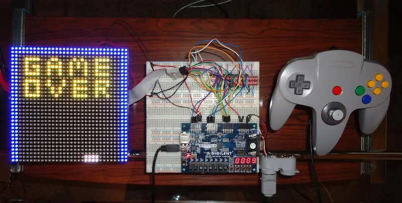
FPGA Pong Game with Nintendo 64 Controller Interface
Objective
In designing this project, my goal was to develop a thorough understanding of FPGA programming and VHDL. I wanted to give myself the challenge of integrating several modules into a coherent, interesting, and educational system that demonstrates the capabilities of a small FPGA, such as the Xilinx Spartan-3E XC3S100E.
Introduction
Having spent over 20 years as a software engineer without ever writing a game, creating a classic Pong clone seemed like the perfect starting point. Every game requires a user interface, which posed the fundamental architectural question: should I drive a standard VGA monitor or design a custom display interface?
Some research led to an intriguing device from Adafruit Industries: a 32×32 RGB LED matrix. The matrix was an attractive choice because it allowed the entire game system to remain compact, portable, and completely self-contained.
I also have a deep passion for retro-gaming and vintage console emulation, and had long wanted to design a custom hardware interface to connect an original Nintendo 64 controller to a PC. As a result, I decided to incorporate a full bi-directional 1-wire serial interface for the Nintendo 64 controller directly into the FPGA design.
System Components
All code for the system was written in VHDL, specifically synthesized and mapped for the Xilinx Spartan-3E XC3S100E FPGA.
The primary hardware components comprising the system are:
- Digilent Basys 2 FPGA Trainer Board (incorporating the Xilinx Spartan-3E XC3S100E in a CP132 package)
- 32×32 RGB LED Matrix (Adafruit Industries)
- 13 MOSFET 5V to 3.3V Bi-Directional Logic Level Translation Modules
- Original Nintendo 64 Controller (NUS-005)
- 50 MHz DIP Crystal Clock Oscillator
Each component is detailed in the sections below.
Digilent Basys 2 Spartan-3E FPGA Trainer Board
The Basys 2 board is an evaluation platform manufactured by Digilent designed for students and engineers to gain hands-on experience with VHDL/Verilog digital design. The board contains multiple slide switches, pushbuttons, LEDs, four expansion PMOD I/O headers, a USB programming/power interface, four 7-segment LED displays, and a VGA port.
The board operates at an I/O and core voltage of 3.3V and includes an onboard silicon-based oscillator running at 50 MHz. Unfortunately, as I discovered early in testing, the stock silicon oscillator does not provide a clean clock signal; its cycle-to-cycle phase jitter is exceedingly high (see Appendix II).
Digilent recommends installing an external clock oscillator for applications requiring strict frequency stability. To eliminate timing ambiguity during asynchronous serial decoding and high-speed matrix multiplexing, I purchased an external 50 MHz crystal oscillator from DigiKey and installed it directly into the unpopulated IC6 socket on the Basys 2 board.
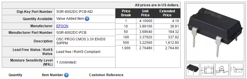 Figure 1: 50 MHz external crystal oscillator.
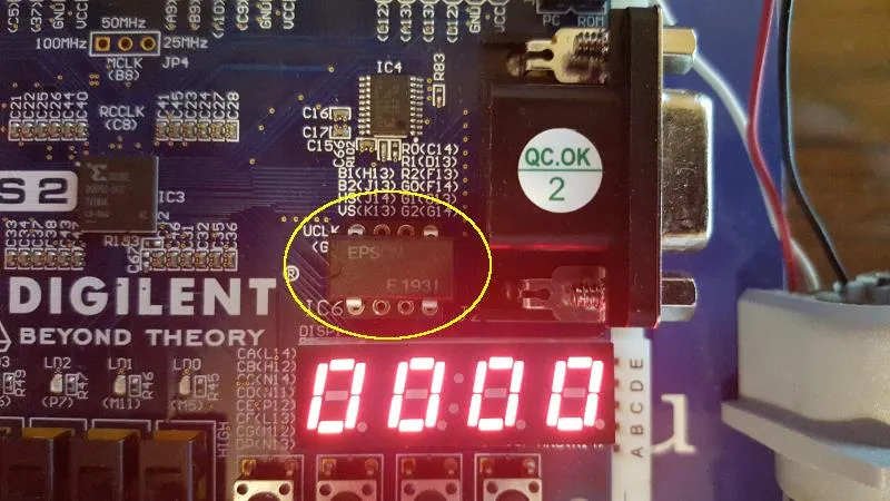 Figure 2: External crystal oscillator installed into socket IC6 on the Basys 2 board.
This modification proved vital: the frequency stability of the crystal clock dramatically improved the reliability of the asynchronous serial decoder and eradicated display jitter.
In terms of I/O, this project utilized virtually every available general-purpose pin on the Basys 2 board, primarily dedicated to driving the matrix rows, columns, and control strobes. The four onboard 7-segment displays were mapped to present the real-time game score, and pushbutton BTN3 was wired to trigger an asynchronous system reset.
32×32 RGB LED Matrix Display
The primary display is a 32×32 RGB LED matrix purchased from Adafruit Industries. Very little official manufacturer documentation was available for these generic panels, though several community engineers had experimented with them and published reverse-engineered timing diagrams and reference VHDL code.
The panel contains 1,024 RGB LEDs arranged in a grid of 32 rows by 32 columns (a total of 3,072 individual LED dies). The matrix is split horizontally into two distinct 16-row banks:
- Top Half: 32 columns × 16 rows (driven by inputs )
- Bottom Half: 32 columns × 16 rows (driven by inputs )
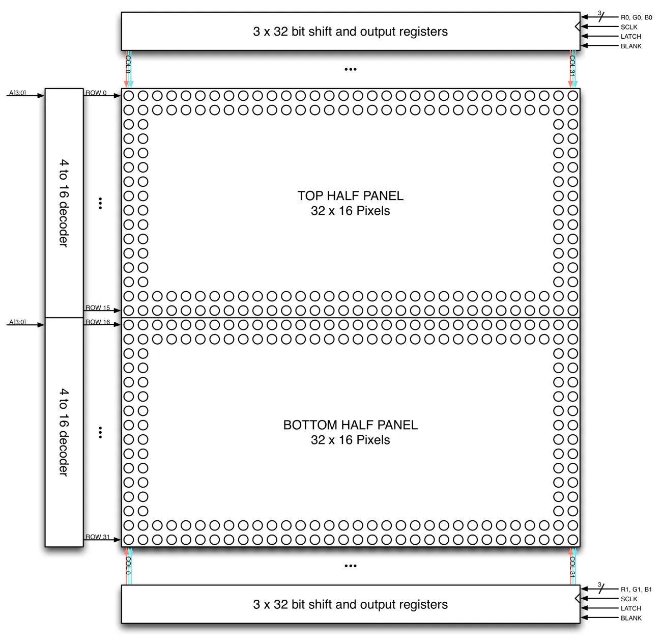 Figure 3: Schematic representation of the 32×32 RGB LED matrix column and row driver organization.
Column and Row Driver Architecture
- Column Drivers: Driven by two sets of three 32-bit shift registers (one set each for red, green, and blue on the upper and lower banks).
- Row Drivers: Driven by a pair of 4-to-16 line decoders controlled by four address select lines ().
To illuminate pixels, two rows (one in the upper half and one in the lower half) are drawn simultaneously:
- The 4-bit row address () is asserted to select the active row pair ( and ).
- 32 clock pulses are applied to
CLK, shifting 32 bits of pixel data into in parallel. - The latch signal (
LAT) is pulsed HIGH to transfer the shift-register contents to the output drivers. - Output Enable (
OE) is driven LOW to illuminate the selected row pair.
By repeating this sequence across all 16 row addresses at high speed, persistence of vision creates a completely flicker-free display. Although each individual LED die is binary (either ON or OFF), pulse-width modulation (PWM) or binary code modulation (BCM) multiplexing can theoretically achieve up to 24-bit true color (16.7 million colors). However, as discussed in the synthesis section, memory limitations on the Spartan-3E necessitated capping the color depth at 3 bits (8 primary saturated colors).
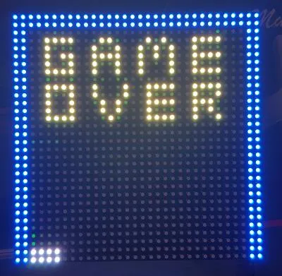 Figure 4: The 32×32 RGB LED matrix displaying the end-game “GAME OVER” message.
Power Consumption
The matrix is powered by an external 5V regulated DC supply. If all 1,024 LEDs were illuminated white at 100% duty cycle, the matrix could consume up to 4.0 A. Because the display is continuously multiplexed across 16 rows, actual operational current draw during gameplay was measured at approximately 200 to 300 mA.
As seen in Figure 4, colors are exceptionally bright and vibrant, though faint bleed-over is visible between neighboring pixels, likely caused by cross-talk between high-speed breadboard jumper leads.
MOSFET 5V-to-3.3V Logic Level Translation
The LED matrix requires 5V TTL/CMOS logic levels for its shift registers and decoders, whereas the Spartan-3E I/O banks on the Basys 2 board operate strictly at 3.3V LVCMOS. Driving 5V inputs directly with 3.3V logic runs the risk of unreliable logic-high threshold detection, while any 5V reflections could damage the FPGA.
To solve this, I incorporated a proven bi-directional level-shifting circuit based on the BSS138 N-channel enhancement-mode MOSFET and pull-up resistors.
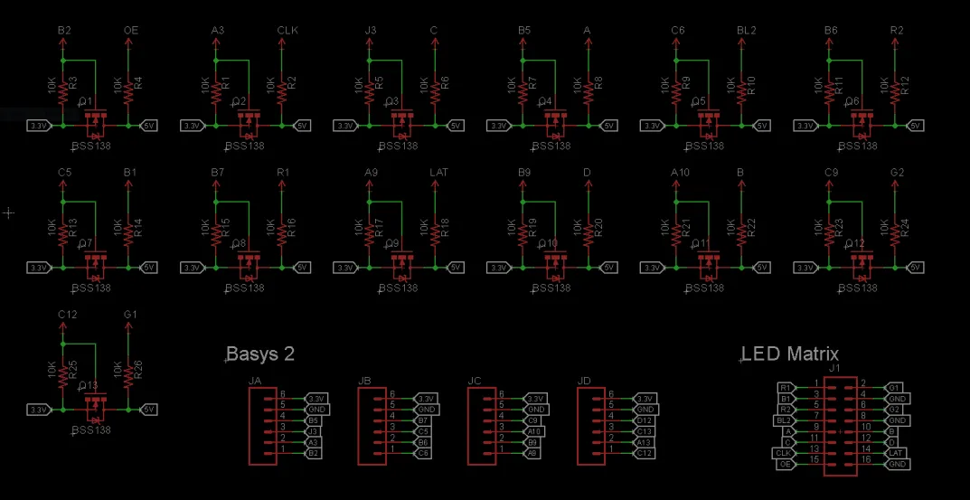 Figure 5: MOSFET bi-directional 5V to 3.3V logic level shifting schematic.
With a MOSFET turn-on rise time of just 9 ns, this circuit easily accommodates multi-megahertz switching frequencies. SparkFun sells pre-assembled 4-channel breakout modules featuring this circuit; I utilized four modules (providing 16 total level-shifted lines, of which 13 were actively assigned).
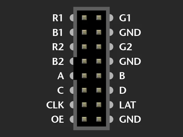 Figure 6: Pinout of the 16-pin dual-row IDC ribbon connector for the 32×32 LED matrix.
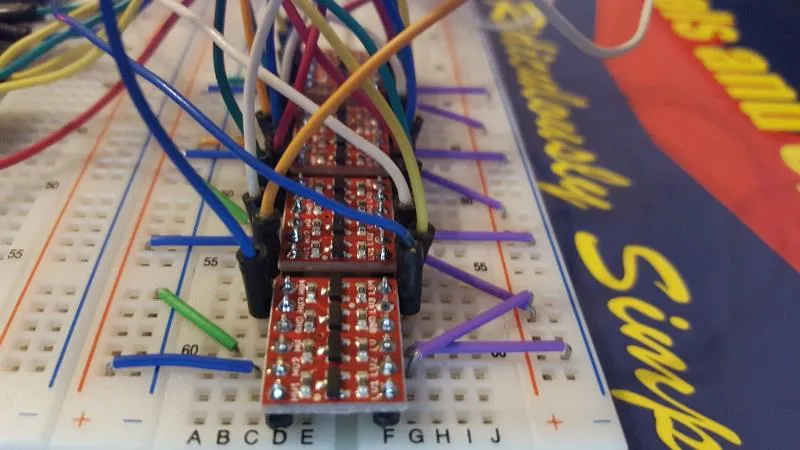 Figure 7: Solderless breadboard layout of the 13 MOSFET level-shifter channels and Basys 2 breakout wiring.
The connections were routed through a solderless breadboard using jumper wires (Figure 7). While completely functional, point-to-point jumpers at a 2.2+ MHz scan rate introduce parasitics and cross-talk, highlighting the importance of dedicated PCB layout in future revisions.
Nintendo 64 Game Controller Interface
Introduced in 1996, the Nintendo 64 controller was the first mainstream console gamepad to feature an optical analog thumbstick alongside digital action buttons.
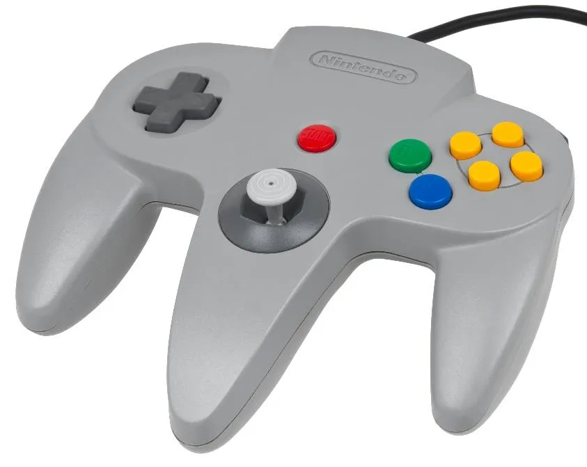 Figure 8: Original Nintendo 64 game controller (NUS-005).
Serial Communication Protocol
The N64 controller communicates with the console over an asynchronous, bi-directional, single-wire serial bus with an external pull-up resistor to 3.3V. Because the controller operates natively at 3.3V logic, it interfaces directly with the Spartan-3E FPGA without requiring voltage translation.
Data bits are encoded using pulse-width modulation at a nominal bit period of (a transmission rate of ):
- Logical ‘0’: Line driven LOW for , followed by HIGH for .
- Logical ‘1’: Line driven LOW for , followed by HIGH for .
- Stop Bit: Line driven LOW for , then released to idle HIGH.
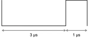 Figure 9: Timing waveform for a logical ‘0’ (3 µs LOW, 1 µs HIGH).
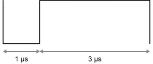 Figure 10: Timing waveform for a logical ‘1’ (1 µs LOW, 3 µs HIGH).
Polling and Response Sequence
To poll the controller state, the host console (in this case, our FPGA) transmits a 9-bit request:
- Command Byte
0x01: Eight bits00000001(request controller status). - Stop Bit: LOW pulse.
The controller responds with a 33-bit packet consisting of 32 data bits followed by a stop bit:
 Figure 11: Oscilloscope capture of the complete polling request followed by the controller’s serial response.
The 32 data bits map directly to the controller’s physical controls:
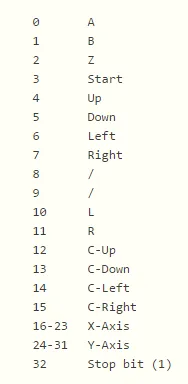 Figure 12: Bit mapping of the 32-bit controller response packet.
- Byte 0 (Bits 0–7): Digital buttons:
A,B,Z,Start,D-Up,D-Down,D-Left,D-Right. - Byte 1 (Bits 8–15): Status flags & buttons:
Reset,(Reserved),L,R,C-Up,C-Down,C-Left,C-Right. - Byte 2 (Bits 16–23): Analog Joystick X-axis deflection (8-bit two’s complement: -128 to +127).
- Byte 3 (Bits 24–31): Analog Joystick Y-axis deflection (8-bit two’s complement: -128 to +127).
While official N64 games poll the controller once per vertical refresh (~16.6 ms to 33 ms), I successfully tested and operated the controller at significantly faster refresh rates. For this project, I chose a continuous 15 ms polling rate, ensuring ultra-low input latency for paddle movement.
 Figure 13: Repetitive 15 ms polling cycle captured on the logic analyzer.
System Design & VHDL Implementation
The complete system architecture was partitioned into discrete, modular VHDL entities:
N64_Controller_Interface: Bi-directional 1-wire serial transceiver, majority-voting bit decoder, and button/joystick register file.rgb_matrix_top_level: Scanline address generator, column shift register serializer, multiplexer, and dual-port video RAM interface.game_engine_top: Pong state machine, 2D vector physics, collision boundary arithmetic, score tracking, and sprite rendering.top_level: System clock prescalers, 7-segment LED display decoder, and top-level pin routing.
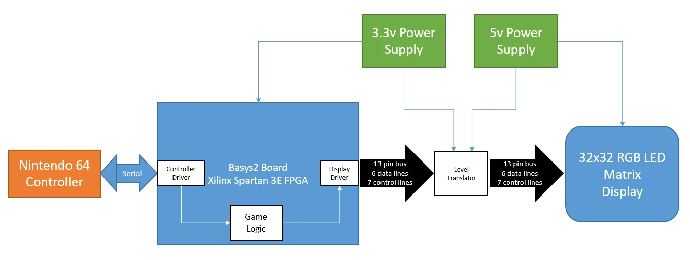 Figure 14: Top-level system block diagram illustrating the interconnect between FPGA modules and external peripherals.
Interfacing the Nintendo 64 Controller: Lessons in Serial Decoding
Decoding the N64 controller stream turned out to be the single most challenging and time-consuming phase of the entire project. Because the controller is driven by its own internal RC clock, the turnaround delay between the FPGA’s poll stop bit and the controller’s first response bit varies considerably from poll to poll.
I evaluated three distinct decoding strategies:
Method 1: Fixed Time Offsets (Failed)
Sample the serial line at fixed intervals () following the completion of the polling command.
- Result: Total failure. Because the response latency from the controller varied on every polling cycle, sampling phase drifted immediately, resulting in corrupt bit reads.
Method 2: Edge-to-Edge Cycle Counting (Failed on Hardware)
Detect each falling edge, start a counter, and measure the duration in clock cycles until the subsequent rising edge is observed. If the LOW pulse duration was , decode a ‘1’; if , decode a ‘0’.
- Result: While this approach simulated flawlessly in Active-HDL (Figure 15), it failed in physical hardware. Breadboard noise and ground bounce produced spurious edge transitions that tricked the counter, causing dropped bits and misaligned packets.
 Figure 15: Active-HDL behavioral timing simulation of the N64 serial decoder.
Method 3: Falling Edge Trigger with Multi-Sample Majority Voting (Successful)
Wait for a legitimate falling edge, pause for a stabilization window, and then acquire five consecutive samples spaced across a window. Sum the sampled values: if the majority of samples are HIGH, decode a ‘1’; otherwise, decode a ‘0’.
- Result: 100% stable. By integrating majority voting across the critical decision window, line noise and minor edge jitter were completely filtered out, delivering flawless packet decoding across thousands of polling cycles.
The controller interface was implemented as a finite state machine (FSM) cycling through IDLE, POLL_TX, LISTEN_WAIT, SAMPLE_BITS, and LATCH_DATA.
Interfacing the 32×32 RGB LED Matrix
The display controller builds upon an open-source Adafruit reference design originally written for a 32×16 display. Adapting the architecture to a 32×32 matrix presented several engineering hurdles:
- 4th Row Address Line (): The 32×16 display required only three address lines () to multiplex 8 dual-row pairs. For a 32×32 matrix with 16 dual-row pairs, I modified the VHDL entity and row decoder to generate a 4-bit binary address ().
- Dot Clock Frequency Tuning: Multiplexing at clock frequencies above 5 MHz caused severe ghosting and pixel ghost artifacts across adjacent columns. I traced this to parasitic capacitance and ringing on the solderless breadboard wiring. Scaling the shift register clock to 5 MHz eliminated the artifacts while maintaining a refresh rate well above human flicker fusion thresholds.
- Color Depth Reduction (24-bit 3-bit): The reference driver supported 24-bit true color by implementing multi-pass binary code modulation. However, buffering a 24-bit frame exceeded the available memory slices on our Spartan-3E XC3S100E. I restructured the video RAM and controller to utilize 3 bits per pixel (1 bit each for Red, Green, and Blue), supporting 8 bright primary colors while fitting comfortably within distributed memory.
- Saleae Logic Analysis: Simulating full matrix refresh frames in Active-HDL was prohibitively slow. To debug the hardware in real-time, I used a Saleae logic analyzer to inspect shift register clocking, latch strobes, output enable duty cycles, and address sequencing (Figure 16).
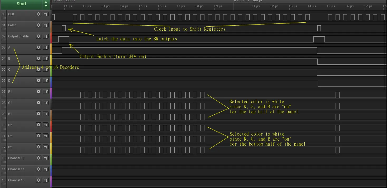 Figure 16: Logic analyzer capture of matrix control signals: shift clock, latch (
LAT), output enable (OE), RGB data lines, and row addresses.
Pong Game Logic, Vector Physics & Coordinate Mapping
The game engine implements single-player Pong on a Cartesian coordinate system:
- Field Boundaries: Bounded on the Left (), Top (), and Right () by solid white walls.
- Loss Condition: The bottom boundary () is open; if the ball passes the paddle and reaches , the ball is dead, scoring halts, and the “GAME OVER” sequence activates.
- Scoring & Difficulty: Each successful paddle deflection increments the score by 1 (displayed on the Basys 2 seven-segment display). To increase challenge, ball velocity doubles at 10 points and doubles again at 15 points.
Game Objects & Dynamics
- Paddle: A horizontal bar 8 pixels wide by 2 pixels high located at . The paddle moves exclusively along the horizontal X-axis, controlled by the N64 analog thumbstick. To provide smooth control, the joystick’s 8-bit unsigned deflection (, where center ) is mapped into three speed thresholds: deadzone (stationary), fine adjustment (), and rapid deflection ().
- Ball: A pixel block whose trajectory is updated every physics frame by a 2D velocity vector: Collisions with the top wall invert , collisions with the side walls invert , and collisions with the player paddle invert and impart deflection momentum based on collision offset (Figure 17).
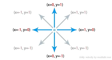 Figure 17: 2D velocity vector inversion mathematics for ball reflections against boundaries and the paddle.
Sprite and Wall ROM Mapping in Excel
The static walls and the 8-color “GAME OVER” banner were mapped into a Xilinx LogiCORE Distributed Memory ROM initialized via a .coe memory file.
To create the sprite graphics, I mapped the matrix cells onto an Excel spreadsheet (Figure 18), assigning binary RGB bit vectors to each cell. Mapping each pixel visually by hand strongly echoed my early teenage years in the 1980s, hand-drawing Sprite bitmasks for Commodore 64 VIC-II games!
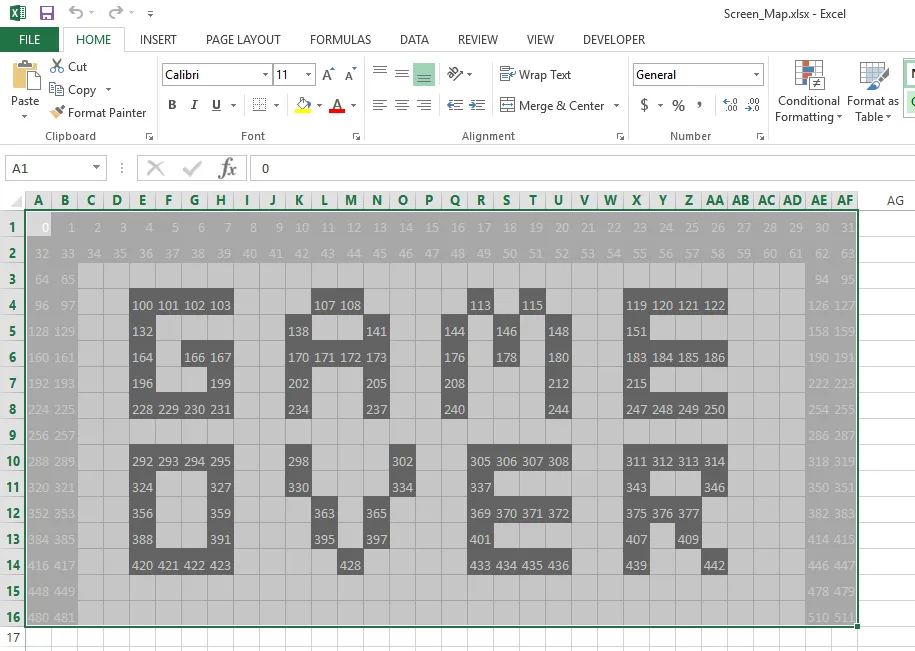 Figure 18: Excel memory map used to calculate
.coe initialization vectors for the walls and “GAME OVER” bitmap.
To maintain clean, structured code, I leveraged VHDL record types and custom package functions extensively (defined in common_pkg.vhd). Grouping coordinates, velocities, and color vectors into unified records mirrored modern object-oriented programming conventions within a synthesizable hardware description.
Synthesis, Timing & 99% FPGA Slice Utilization
From the outset, fitting an entire Pong game engine, asynchronous serial transceiver, video frame buffer, and 32×32 display driver onto a 100k-gate Xilinx Spartan-3E XC3S100E was a high-stakes challenge.
As the final modules were integrated, the design repeatedly exceeded the physical slice budget. I implemented several rigorous optimization passes to bring the design under the device limit:
- Color Depth Pruning: Reduced frame buffer pixel storage from 24 bits to 3 bits per pixel, saving hundreds of distributed RAM slices.
- Integer Range Clamping: Constrained all VHDL
integersignals and record variables to strict minimal ranges (e.g.,integer range 0 to 31for coordinates; clamping the maximum score counter from9999down to999). Unconstrained 32-bit integers instantiate excessive arithmetic carry chains and flip-flops. - Redundant Register Stripping: Pruned intermediate pipeline registers and consolidated combinational logic in the rendering state machine.
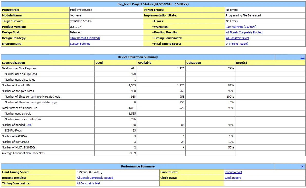 Figure 19: Xilinx ISE Device Utilization Summary showing 958 out of 960 slices occupied (99.79%).
As documented in the ISE Device Utilization Summary (Figure 19):
- Occupied Slices: 958 out of 960 (99%)
- Slice Flip-Flops: 585 out of 1,920 (30%)
- 4-input LUTs: 1,385 out of 1,920 (72%)
- Bonded IOBs: 27 out of 83 (32%)
The design utilized virtually 100% of the XC3S100E’s available logic slices—there was practically zero space left for any additional features!
Hardware Quirks & Synthesis Notes
The Display Clock Dropout Bug
During testing, I encountered a peculiar hardware anomaly: occasionally, after making a minor code tweak and rebuilding the bitstream, the LED matrix would fail to power on. Probing the matrix clock line with an oscilloscope revealed no clock output whatsoever. Interestingly, slightly bumping the display clock divider frequency up or down by a single step immediately restored normal clock generation. Despite extensive debugging, I could find no root cause in the RTL; adjusting the clock prescaler remained the reliable operational workaround.
ISE 14.7 vs. Modern Toolchains
Targeting the legacy Spartan-3E required using Xilinx ISE 14.7. Eliminating all synthesis warnings in ISE proved nearly impossible, and official documentation was sparse given the industry’s transition to Vivado. However, careful timing constraint authoring in the .ucf file ensured all setup and hold times were met at 50 MHz.
Conclusion
EE 5143 was my first formal introduction to VHDL and hardware description languages. Coming from a 20-year career in pure software engineering, designing for concurrent hardware logic required a fundamental shift in mindset.
Synthesizing a complete, real-time gaming system that directly couples an original Nintendo 64 controller to a high-speed LED matrix was an immensely rewarding journey. Pushing a 100k-gate Spartan-3E FPGA to 99% slice utilization taught me invaluable lessons in hardware pipelining, resource optimization, clock domain management, and signal integrity that continue to inform my engineering practice.
Appendix I – Timing Diagrams for the Display and N64 Controller
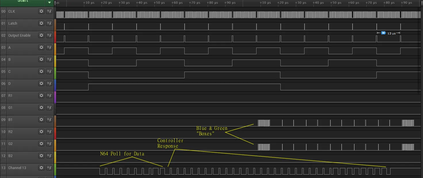 Figure 20: Comprehensive logic analyzer capture showing the concurrent N64 controller polling sequence alongside active RGB matrix scanline multiplexing.
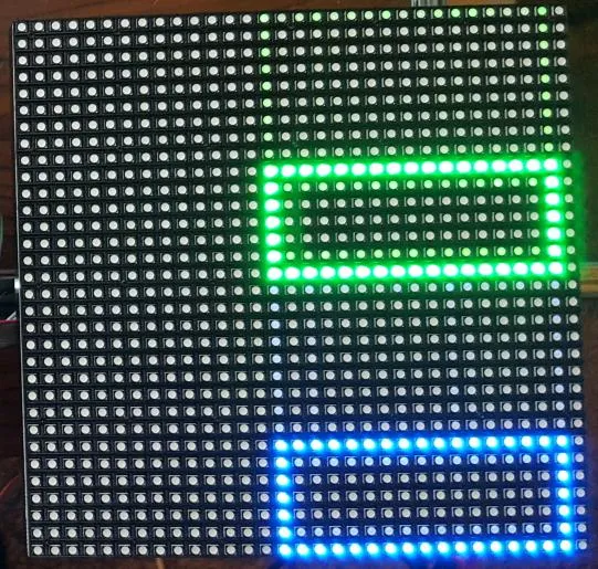 Figure 21: 32×32 LED matrix executing hardware test patterns: static blue and green boundary rectangles.
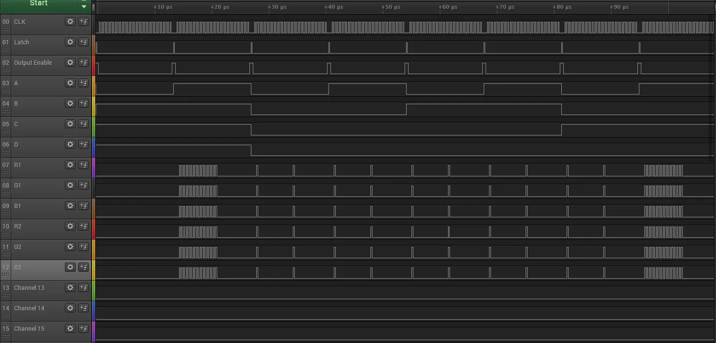 Figure 22: Logic analyzer timing diagram capturing the shift-register serial stream during dual white rectangle rendering.
Appendix II – Improvements Realized with the Crystal Oscillator
The Basys 2 board includes an onboard silicon oscillator running at 50 MHz. While adequate for basic classroom counter experiments, its phase jitter was severe enough to cause false triggers and bit slips in the asynchronous N64 serial decoder.
Installing a dedicated 50 MHz DIP crystal oscillator into socket IC6 transformed the system’s clock stability:
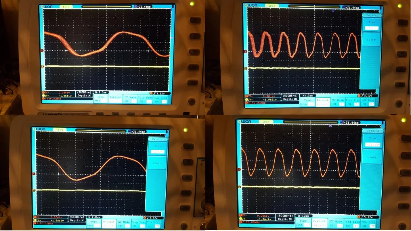 Figure 23: Digital Storage Oscilloscope (DSO) comparison: The upper waveforms show extreme phase jitter on the onboard silicon oscillator; the lower waveforms illustrate the razor-sharp edges and negligible jitter of the 50 MHz DIP crystal oscillator.
Appendix III – Complete VHDL Source Code
Below is the design hierarchy and full synthesizable VHDL source code for all 13 project modules.
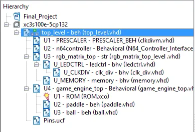 Figure 24: Module hierarchy tree in Xilinx ISE Project Navigator.
- Top_level.vhd — System Top-Level Integration & Pin Routing
library IEEE;
use IEEE.STD_LOGIC_1164.ALL;
use IEEE.NUMERIC_STD.ALL;
use IEEE.std_logic_unsigned.all;
use work.rgbmatrix.all; -- Constants & Configuration
use work.common_pkg.all;
entity top_level is
Port ( CLK : in std_logic;
RST : in std_logic := '0';
serial : inout std_logic := 'Z';
clk_out : out std_logic;
r1 : out std_logic;
r2 : out std_logic;
b1 : out std_logic;
b2 : out std_logic;
g1 : out std_logic;
g2 : out std_logic;
aa : out std_logic;
bb : out std_logic;
cc : out std_logic;
dd : out std_logic;
lat : out std_logic;
oe : out std_logic;
Contr : out std_logic_vector (7 downto 0);
an : out std_logic_vector(3 downto 0);
seg : out std_logic_vector (7 downto 0);
debug : out std_logic_vector (1 downto 0));
end top_level;
architecture beh of top_level is
component PRESCALER
port (CLK: in STD_LOGIC;
MR: in STD_LOGIC;
CLKDIVN : out STD_LOGIC
);
end component;
component n64controller

port( MCLK : in std_logic;
RST: in std_logic := '0';
serial : inout std_logic;
A : out std_logic;
B : out std_logic;
Z : out std_logic;
Start : out std_logic;
D_Up : out std_logic;
D_Down : out std_logic;
D_Left : out std_logic;
D_Right :out std_logic;
L : out std_logic;
R : out std_logic;
C_Up : out std_logic;
C_Down : out std_logic;
C_Left : out std_logic;
C_Right: out std_logic;
Joy_X : out std_logic_vector (7 downto 0);
Joy_Y : out std_logic_vector (7 downto 0);
debug : out std_logic_vector (1 downto 0));
end component;
component rgb_matrix_top
port (
clk_in : in std_logic;
rst_n : in std_logic;
clk_out : out std_logic;
r1 : out std_logic;
r2 : out std_logic;
b1 : out std_logic;
b2 : out std_logic;
g1 : out std_logic;
g2 : out std_logic;
a : out std_logic;
b : out std_logic;
c : out std_logic;
d : out std_logic;
lat : out std_logic;
oe : out std_logic;
data_incoming : in std_logic_vector(DATA_WIDTH-1 downto 0);
data_valid : in std_logic
);
end component;
component game_engine_top
port (
CLK : in STD_LOGIC;
RST : in STD_LOGIC;
Joy_X : in STD_LOGIC_VECTOR (7 downto 0);
display_out : out std_logic_vector(DATA_WIDTH-1 downto 0);
display_data_valid : out std_logic;
score : out integer range 0 to 999
);
end component;
signal MCLK : std_logic;
signal A : std_logic;
signal B : std_logic;
signal Z : std_logic;
signal Start : std_logic;
signal D_Up : std_logic;
signal D_Down : std_logic;
signal D_Left : std_logic;
signal D_Right :std_logic;
signal L : std_logic;
signal R : std_logic;
signal C_Up : std_logic;
signal C_Down : std_logic;
signal C_Left : std_logic;
signal C_Right: std_logic;
signal Joy_X : std_logic_vector (7 downto 0);

signal Joy_Y : std_logic_vector (7 downto 0);
signal data_incoming : std_logic_vector(DATA_WIDTH-1 downto 0);
signal data_valid : std_logic;
signal score : integer range 0 to 999;
signal mhertz_count : std_logic_vector(5 downto 0);
--signal khertz_count : std_logic_vector(9 downto 0);
--signal mhertz_en : std_logic ;
--signal khertz_en : std_logic ;
signal segment_data : led;
begin
Contr <= Joy_X;
U1: PRESCALER
port map (CLK=>CLK,
MR=>RST,
CLKDIVN=>MCLK);
U2: n64controller
port map (MCLK=>MCLK,
RST=>RST,
serial=>serial,
A=>A,
B=>B,
Z=>Z,
Start=>Start,
D_Up=>D_Up,
D_Down=>D_Down,
D_Left=>D_Left,
D_Right=>D_Right,
L=>L,
R=>R,
C_Up=>C_Up,
C_Down=>C_Down,
C_Left=>C_Left,
C_Right=>C_Right,
Joy_X=>Joy_X,
Joy_Y=>Joy_Y,
debug=>debug);
U3: rgb_matrix_top
port map (clk_in=>CLK,
rst_n=>RST,
clk_out=>clk_out,
r1=>r1,
r2=>r2,
b1=>b1,
b2=>b2,
g1=>g1,
g2=>g2,
a=>aa,
b=>bb,
c=>cc,
d=>dd,
lat=>lat,
oe=>oe,
data_incoming=>data_incoming,
data_valid=>data_valid
);
U4: game_engine_top
port map (CLK=>CLK,
RST=>RST,
Joy_X=>Joy_X,
display_out=>data_incoming,
display_data_valid=>data_valid,
score=>score
);
-- generates a 1 Mhz signal from a 50 Mhz signal

process (CLK, RST)
begin
if rst = '1' then
mhertz_count <= (others => '0');
mhertz_en <= '0';
elsif rising_edge(CLK) then
mhertz_count <= mhertz_count + 1;
if mhertz_count = "110010" then
mhertz_en <= '1';
mhertz_count <= (others => '0');
else
mhertz_en <= '0';
end if ;
end if ;
end process ;
-- generates a 1 kHz signal from a 1Mhz signal
process (CLK, RST)
begin
if rst = '1' then
khertz_count <= (others => '0');
khertz_en <= '0';
elsif rising_edge(CLK) then
if mhertz_en = '1' then
khertz_count <= khertz_count + 1;
if khertz_count = "1111101000" then
khertz_en <= '1';
khertz_count <= (others => '0');
else
khertz_en <= '0';
end if ;
else
khertz_en <= '0';
end if ;
end if;
end process;
process(CLK,RST)
variable cd : std_logic_vector(1 downto 0):= "00";
begin
if RST = '1' then
an <= "0000";
seg <= "11000000";
elsif rising_edge(CLK) then
if khertz_en = '1' then
cd(1 downto 0) := cd(1 downto 0) + 1 ;
end if ;
if cd="00" then
an<="0111";
case segment_data.segment0 is
when "0000" => seg <= "11000000";
when "0001" => seg <= "11111001";
when "0010" => seg <= "10100100";
when "0011" => seg <= "10110000";
when "0100" => seg <= "10011001";
when "0101" => seg <= "10010010";
when "0110" => seg <= "10000010";
when "0111" => seg <= "11111000";
when "1000" => seg <= "10000000";
when "1001" => seg <= "10010000";
when others => seg <= "11000000";
end case ;
elsif cd="01" then
an<="1011";
case segment_data.segment1 is
when "0000" => seg <= "11000000";

when "0001" => seg <= "11111001";
when "0010" => seg <= "10100100";
when "0011" => seg <= "10110000";
when "0100" => seg <= "10011001";
when "0101" => seg <= "10010010";
when "0110" => seg <= "10000010";
when "0111" => seg <= "11111000";
when "1000" => seg <= "10000000";
when "1001" => seg <= "10010000";
when others => seg <= "11000000";
end case ;
elsif cd="10" then
an<="1101";
case segment_data.segment2 is
when "0000" => seg <= "11000000";
when "0001" => seg <= "11111001";
when "0010" => seg <= "10100100";
when "0011" => seg <= "10110000";
when "0100" => seg <= "10011001";
when "0101" => seg <= "10010010";
when "0110" => seg <= "10000010";
when "0111" => seg <= "11111000";
when "1000" => seg <= "10000000";
when "1001" => seg <= "10010000";
when others => seg <= "11000000";
end case ;
elsif cd="11" then
an<="1110";
case segment_data.segment3 is
when "0000" => seg <= "11000000";
when "0001" => seg <= "11111001";
when "0010" => seg <= "10100100";
when "0011" => seg <= "10110000";
when "0100" => seg <= "10011001";
when "0101" => seg <= "10010010";
when "0110" => seg <= "10000010";
when "0111" => seg <= "11111000";
when "1000" => seg <= "10000000";
when "1001" => seg <= "10010000";
when others => seg <= "11000000";
end case ;
end if;
end if;
end process;
process (score)
variable tmp_score : led;
begin
if rising_edge(CLK) then
segment_data <= int_to_led(score);
end if;
end process;
end beh;
- clkdivm.vhd — Master 50 MHz to 1 MHz Clock Prescaler
Library IEEE;
use IEEE.STD_LOGIC_1164.all;
use IEEE.STD_LOGIC_UNSIGNED.all;
entity PRESCALER is
port (CLK: in STD_LOGIC;
MR: in STD_LOGIC;
CLKDIVN: out STD_LOGIC
);
end PRESCALER;

architecture PRESCALER_BEH of PRESCALER is
signal QOUT: integer := 0;
signal intreset: STD_LOGIC := '0';
signal toggle : std_logic := '0';
begin
process (CLK, MR, intreset)
begin
if MR = '1' or intreset = '1' then
QOUT <= 0;
intreset <= '0';
else
if rising_edge(CLK) then
if QOUT >= 1 then
intreset <= '1';
case toggle is
when '0' => toggle <= '1';
when '1' => toggle <= '0';
when others => toggle <= '1';
end case;
else
intreset <= '0';
end if;
QOUT <= QOUT + 1;
end if;
end if;
end process;
CLKDIVN <= toggle;
end PRESCALER_BEH;
- N64_Controller_Interface.vhd — Bi-Directional 1-Wire N64 Serial Decoder
library IEEE;
use IEEE.STD_LOGIC_1164.ALL;
use IEEE.NUMERIC_STD.ALL;
entity n64controller is
port( MCLK : in std_logic;
RST: in std_logic := '0';
serial : inout std_logic;
A : out std_logic;
B : out std_logic;
Z : out std_logic;
Start : out std_logic;
D_Up : out std_logic;
D_Down : out std_logic;
D_Left : out std_logic;
D_Right :out std_logic;
L : out std_logic;
R : out std_logic;
C_Up : out std_logic;
C_Down : out std_logic;
C_Left : out std_logic;
C_Right: out std_logic;
Joy_X : out std_logic_vector (7 downto 0);
Joy_Y : out std_logic_vector (7 downto 0);
debug : out std_logic_vector (1 downto 0) := "00");
end n64controller;
architecture Behavioral of n64controller is
signal controller : std_logic_vector (0 to 32) := "000000000000000000000000000000000";
--32 bits and one stop bit at the end
begin

process (MCLK, RST)
-- State Machine Variables
variable clkcount : integer := 0;
type state_type is (idle,poll,listen); --type of state machine.
variable current_s : state_type := idle; -- current state declaration.
variable poll_vector : std_logic_vector (0 to 35) := "000100010001000100010001000101110111";
variable poll_index : integer := 0;
variable pcount : integer := 0;
variable idx : integer := 0;
variable sample_count : integer := 0;
variable sampling : boolean := false;
variable sample_value : integer := 0;
begin
if rising_edge(MCLK) then
if RST='1' then
clkcount := 0;
current_s := idle;
else
case current_s is
when idle =>
--when current state is "idle"
--if clkcount > 374999 then
if clkcount > 187499 then
current_s := poll;
serial <= 'Z';
clkcount := 0;
poll_index := 0;
pcount := 0;
idx := 0;
sample_count := 0;
sampling := false;
else
clkcount := clkcount + 1;
end if;
when poll =>
--when current state is "poll"
if clkcount > 447 then --subtracted a few cycles
since the controller responds early
current_s := listen;
serial <= 'Z';
clkcount := 0;
poll_index := 0;
pcount := 0;
idx := 0;
sample_count := 0;
sampling := false;
else
if pcount = 0 then
serial <= poll_vector(poll_index);
pcount := pcount + 1;
elsif pcount = 12 then
poll_index := poll_index + 1;
pcount := 0;
else
pcount := pcount + 1;
end if;
clkcount := clkcount + 1;
end if;
when listen =>
--when current state is "listen"
if clkcount > 1615 then
current_s := idle;
serial <= 'Z';
clkcount := 0;
poll_index := 0;
pcount := 0;
idx := 0;
sample_count := 0;
sampling := false;
else
if (serial = '0' or serial = 'L') and
sampling = false then --start the whole process

sample_count := 0;
sampling := true;
end if;
if sample_count >= 25 and sample_count < 30 then --we take five samples
if serial = '1' then
sample_value := sample_value + 1;
end if;
end if;
if sample_count = 30 then
if sample_value > 3 then --if the
majority are ones...then we have a one
controller(idx) <= '1';
else
controller(idx) <= '0';
end if;
idx := idx + 1;
sample_value := 0;
debug(1) <= '1';
else
debug(1) <= '0';
end if;
sample_count := sample_count + 1;
if sample_count = 49 then
sample_count := 0;
end if;
clkcount := clkcount + 1;
end if;
debug(0)<=serial;
end case;
end if;
end if;
end process;
A <= controller(0);
B <= controller(1);
Z <= controller(2);
Start <= controller(3);
D_Up <= controller(4);
D_Down <= controller(5);
D_Left <= controller(6);
D_Right <= controller(7);
L <= controller(10);
R <= controller(11);
C_Up <= controller(12);
C_Down <= controller(13);
C_Left <= controller(14);
C_Right <= controller(15);
Joy_X(7) <= controller(16);
Joy_X(6) <= controller(17);
Joy_X(5) <= controller(18);
Joy_X(4) <= controller(19);
Joy_X(3) <= controller(20);
Joy_X(2) <= controller(21);
Joy_X(1) <= controller(22);
Joy_X(0) <= controller(23);
Joy_Y(7) <= controller(24);
Joy_Y(6) <= controller(25);
Joy_Y(5) <= controller(26);
Joy_Y(4) <= controller(27);
Joy_Y(3) <= controller(28);
Joy_Y(2) <= controller(29);
Joy_Y(1) <= controller(30);
Joy_Y(0) <= controller(31);
end Behavioral;
- game_engine_top.vhd — Pong State Machine, Sprite Renderer & Video RAM Arbiter
library IEEE;
use IEEE.STD_LOGIC_1164.ALL;
use work.rgbmatrix.all; -- Constants & Configuration
use work.common_pkg.all;
use IEEE.NUMERIC_STD.ALL;
entity game_engine_top is
Port ( CLK : in STD_LOGIC;
RST : in STD_LOGIC;
Joy_X : in STD_LOGIC_VECTOR (7 downto 0);
display_out : out std_logic_vector(DATA_WIDTH-1 downto 0);
display_data_valid : out std_logic;
score : out integer range 0 to 999
);
end game_engine_top;
architecture Behavioral of game_engine_top is
signal a : STD_LOGIC_VECTOR(8 DOWNTO 0);
signal qspo : STD_LOGIC_VECTOR(5 DOWNTO 0);
signal paddle_vel : velocity_vector;
signal tmp_paddle : type_paddle;
signal tmp_ball : type_ball;
COMPONENT ROM
PORT (
a : IN STD_LOGIC_VECTOR(8 DOWNTO 0);
clk : IN STD_LOGIC;
qspo : OUT STD_LOGIC_VECTOR(5 DOWNTO 0)
);
END COMPONENT;
component paddle
port ( CLK : in std_logic;
RST : in std_logic;
Joy_X : in STD_LOGIC_VECTOR (7 downto 0);
paddle_struct : inout type_paddle
);
end component;
component ball
port ( CLK : in std_logic;
RST : in std_logic;
paddle_struct : in type_paddle;
ball_struct : inout type_ball;
score : out integer range 0 to 999
);
end component;
-- Memory signals
signal addr : std_logic_vector(ADDR_WIDTH-1 downto 0);
begin
U1 : ROM
PORT MAP (
a => a,
clk => CLK,
qspo => qspo
);
U2: paddle
port map (
CLK=>CLK,
RST=>RST,

Joy_X => Joy_X,
paddle_struct=>tmp_paddle
);
U3: ball
port map (
CLK=>CLK,
RST=>RST,
paddle_struct=>tmp_paddle,
ball_struct=>tmp_ball,
score=>score
);
process (CLK, RST)
-- State Machine Variables
variable clkcount : integer := 0;
type state_type is (idle,update_display); --type of state machine.
variable current_s : state_type := idle; -- current state declaration.
variable index : integer := 1;
variable flip : std_logic := '0';
variable scrpos : screen_pos;
variable scrpos2 : screen_pos;
variable bkgnd : STD_LOGIC_VECTOR(5 DOWNTO 0);
begin
if rising_edge(CLK) then
if RST='1' then
clkcount := 0;
current_s := idle;
index := 1;
else
case current_s is
when idle =>
--when current state is "idle"
if clkcount > 10000 then
current_s := update_display;
clkcount := 0;
else
clkcount := clkcount + 1;
end if;
display_data_valid <= '0';
when update_display =>
--when current state is
"update_display"
if clkcount > 1023 then
current_s := idle;
clkcount := 0;
index := 1;
else
if flip = '0' then
-- Draw the walls
a <= std_logic_vector(to_unsigned(index, 9));
-- If the game is over, display the "GAME OVER" data encoded in yellow "110000"
if tmp_ball.color = "000" then
bkgnd := qspo;
else
if qspo = "110000" then
bkgnd := "000000";
else
bkgnd := qspo;
end if;
end if;
display_out <= bkgnd;
-- Draw the paddle
for I in 0 to 7 loop
scrpos2 := xy_to_screen(tmp_paddle.pos(I), tmp_paddle.color);
if index = scrpos2.index + 1 then
display_out <= scrpos2.color;
end if;

end loop;
-- Draw the ball
for I in 0 to 3 loop
scrpos := xy_to_screen(tmp_ball.pos(I), tmp_ball.color);
-- we need to check if the paddle is in the same pixel space
-- then OR the results together to avoid flicker
if index = scrpos.index + 1 then
for I in 0 to 7 loop
scrpos2 := xy_to_screen(tmp_paddle.pos(I), tmp_paddle.color);
if scrpos.index = scrpos2.index then
scrpos.color := scrpos.color or scrpos2.color;
end if;
end loop;
display_out <= scrpos.color or bkgnd;
end if;
end loop;
-- Set the data as valid
display_data_valid <= '1';
index := index + 1;
if index = 512 then
index := 0;
end if;
else
display_data_valid <= '0';
end if;
flip := not flip;
clkcount := clkcount + 1;
end if;
end case;
end if;
end if;
end process;
end Behavioral;
- paddle.vhd — User Paddle Position Controller & Analog Speed Mapper
Library IEEE;
use IEEE.STD_LOGIC_1164.all;
use IEEE.NUMERIC_STD.ALL;
use work.common_pkg.all;
entity paddle is
port (CLK : in std_logic;
RST : in std_logic;
Joy_X : in STD_LOGIC_VECTOR (7 downto 0);
paddle_struct : inout type_paddle
);
end paddle;
architecture beh of paddle is
signal paddle_speed : integer range 0 to 2000000 := 2000000;
begin
process (CLK, RST)
variable val : integer range -128 to 127;
variable clkcount : integer range 0 to 1500001 := 0;

begin
if RST = '1' then
paddle_struct.pos <= init_paddle_points;
paddle_struct.velocity <= init_velocity_vector;
paddle_struct.color <= "111";
else
if rising_edge(CLK) then
if clkcount > paddle_speed then
clkcount := 0;
val := to_integer(signed(Joy_X));
if val < -8 then
paddle_struct.velocity.x <= -1;
if paddle_struct.pos(0).x > 2 then
for I in 0 to 7 loop
paddle_struct.pos(I).x <= paddle_struct.pos(I).x - 1;
end loop;
end if;
end if;
if val > 8 then
paddle_struct.velocity.x <= 1;
if paddle_struct.pos(0).x < 26 then
for I in 0 to 7 loop
paddle_struct.pos(I).x <= paddle_struct.pos(I).x + 1;
end loop;
end if;
end if;
else
clkcount := clkcount + 1;
end if;
end if;
end if;
end process;
-- Speed signals
paddle_speed <= 100000 when abs(to_integer(signed(Joy_X))) > 96 else
300000 when abs(to_integer(signed(Joy_X))) > 64 else
750000 when abs(to_integer(signed(Joy_X))) > 32 else
2000000;
end beh;
- ball.vhd — 2D Ball Vector Dynamics & Boundary Collision Reflector
library IEEE;
use IEEE.STD_LOGIC_1164.ALL;
use IEEE.NUMERIC_STD.ALL;
use work.common_pkg.all;
entity ball is
port(
CLK : in std_logic;
RST : in std_logic;
paddle_struct : in type_paddle;
ball_struct : inout type_ball;
score : out integer range 0 to 999
);
end ball;
architecture beh of ball is
signal ball_speed : integer range 0 to 1500000 := 1500000;
signal tmp_score : integer range 0 to 999 := 0;
begin
process (CLK, RST)

variable clkcount : integer range 0 to 1500001 := 0;
variable col : collision;
variable xvel_count : integer range 0 to 4 := 0;
variable yvel_count : integer range 0 to 4 := 0;
begin
if RST = '1' then
ball_struct.color <= "100";
ball_struct.pos <= init_ball_points;
ball_struct.velocity <= init_velocity_vector;
tmp_score <= 0;
else
if rising_edge(CLK) then
if ball_struct.color /= "000" then
if clkcount > ball_speed then
clkcount := 0;
if col.is_bottom = '1' and col.is_paddle = '0'
then
-- Game over
ball_struct.color <= "000";
else
if xvel_count = 0 then
for I in 0 to 3 loop
ball_struct.pos(I).x <= ball_struct.pos(I).x + ball_struct.velocity.x;
end loop;
xvel_count := col.new_velocity.x;
else
xvel_count := xvel_count - 1;
end if;
if yvel_count = 0 then
for I in 0 to 3 loop
ball_struct.pos(I).y <= ball_struct.pos(I).y + ball_struct.velocity.y;
end loop;
else
yvel_count := yvel_count - 1;
end if;
end if;
elsif clkcount = ball_speed then
-- Check for a collision
col := collision_check( ball_struct, paddle_struct
);
ball_struct.velocity <= col.new_velocity;
if col.is_collision = '1' then
xvel_count := 0;
xvel_count := 0;
end if;
--paddle_collision <= col.is_bottom and
col.is_paddle;
if col.is_collision = '1' and col.is_bottom = '1'
and col.is_paddle = '1' then
tmp_score <= tmp_score + 1;
end if;
-- Check the score for the ball speed to increase
if tmp_score > 15 then
ball_speed <= 250000;
elsif tmp_score > 9 then
ball_speed <= 750000;
else
ball_speed <= 1500000;
end if;
clkcount := clkcount + 1;
else
clkcount := clkcount + 1;
end if;
end if;
end if;
end if;
end process;
score <= tmp_score;

end beh;
- common_pkg.vhd — Global Types, 2D Points, Velocity Vectors & Math Functions
---------

Package File Template
Purpose: This package defines supplemental types, subtypes,
constants, and functions
To use any of the example code shown below, uncomment the lines and modify as necessary

library IEEE;
use IEEE.STD_LOGIC_1164.all;
use IEEE.NUMERIC_STD.ALL;
package common_pkg is
-- 2d points
type point_2d is
record
x : integer range 0 to 32;
y : integer range 0 to 32;
end record;
constant init_point_2d: point_2d := (x => 0, y => 0);
-- velocity vector
type velocity_vector is
record
x : integer range -2 to 2;
y : integer range -2 to 2;
end record;
constant init_velocity_vector: velocity_vector := (x => 1, y => 1);
-- paddle shape
type paddle_pts is array(0 to 7) of point_2d;
constant init_paddle_points: paddle_pts := ((x=>2,y=>30),(x=>3,y=>30),(x=>4,y=>30),(x=>5,y=>30),(x=>2,y=>31),(x=>3,y=>31),(x=>4,y=>31),(x=>5,y=>31));
-- position, color
type type_paddle is
record
pos : paddle_pts;
velocity : velocity_vector;
color : std_logic_vector(2 downto 0);
end record;
-- ball shape
type ball_pts is array(0 to 3) of point_2d;
constant init_ball_points: ball_pts := ((x=>5,y=>3),(x=>6,y=>3),(x=>5,y=>4),(x=>6,y=>4));
-- position, color, velocity
type type_ball is
record
pos : ball_pts;
velocity : velocity_vector;
color : std_logic_vector(2 downto 0);
end record;
type screen_pos is
record
index : integer range 0 to 511;
color : std_logic_vector(5 downto 0);
end record;
type collision is

record
new_velocity : velocity_vector;
is_collision : std_logic;
is_bottom : std_logic;
is_paddle : std_logic;
end record;
type led is
record
segment0 : std_logic_vector(3 downto 0);
segment1 : std_logic_vector(3 downto 0);
segment2 : std_logic_vector(3 downto 0);
segment3 : std_logic_vector(3 downto 0);
end record;
---- Function to translate x and y into screen coordinates
function xy_to_screen ( point : point_2d;
color : std_logic_vector(2
downto 0) ) return screen_pos;
---- Function to check for collisions with the walls and paddle
function collision_check ( ball : type_ball;
paddle : type_paddle
) return collision;
---- Function to convert an integer into segments for the display
function int_to_led ( val : integer range 0 to 9999 ) return led;
end common_pkg;
package body common_pkg is
---- Function to convert an integer into segments for the display
function int_to_led ( val : integer range 0 to 9999 ) return led is
variable tmp1 : integer range 0 to 9999;
variable tmp2 : integer range 0 to 9999;
variable seg : led;
begin
tmp1 := val / 1000;
seg.segment0 := std_logic_vector(to_unsigned(tmp1, 4));
tmp1 := val - tmp1 * 1000;
tmp2 := tmp1;
tmp1 := tmp1 / 100;
seg.segment1 := std_logic_vector(to_unsigned(tmp1, 4));
tmp1 := tmp2 - tmp1 * 100;
tmp2 := tmp1;
tmp1 := tmp1 / 10;
seg.segment2 := std_logic_vector(to_unsigned(tmp1, 4));
tmp1 := tmp2 - tmp1 * 10;
seg.segment3 := std_logic_vector(to_unsigned(tmp1, 4));
return seg;
end int_to_led;
---- Function to translate x and y into screen coordinates
function xy_to_screen ( point : point_2d;
color : std_logic_vector(2
downto 0) ) return screen_pos is
variable scr_pos : screen_pos;
variable temp : std_logic_vector(5 downto 0) := "000000";
begin
if point.y < 16 then
scr_pos.index := point.y * 32 + point.x;
scr_pos.color := color and "000111";
scr_pos.color := std_logic_vector(unsigned(scr_pos.color) sll 3);
else

scr_pos.index := point.y * 32 - 512 + point.x;
scr_pos.color := color and "000111";
end if;
return scr_pos;
end xy_to_screen;
---- Function to check for collisions with the walls and paddle
function collision_check ( ball : type_ball;
paddle : type_paddle
) return collision is
variable col : collision;
begin
-- Check for a collision with the top left corner
if ball.pos(0).y = 2 and ball.pos(0).x = 2 then
col.new_velocity.x := 2;
col.new_velocity.y := 1;
col.is_collision := '1';
col.is_bottom := '0';
col.is_paddle := '0';
-- Check for a collision with the top right corner
elsif ball.pos(0).y = 2 and ball.pos(0).x = 28 then
col.new_velocity.x := -2;
col.new_velocity.y := 1;
col.is_collision := '1';
col.is_bottom := '0';
col.is_paddle := '0';
-- Check for a collision with the top wall
elsif ball.pos(0).y = 2 then
col.new_velocity.x := ball.velocity.x;
col.new_velocity.y := -ball.velocity.y;
col.is_collision := '1';
col.is_bottom := '0';
col.is_paddle := '0';
-- Check for a collision with the bottom right corner and paddle
elsif ball.pos(0).y = 28 and ball.pos(0).x = 28 then
if paddle.pos(0).x > ball.pos(0).x - 4 and paddle.pos(0).x < ball.pos(0).x + 3 then
col.new_velocity.x := -2;
col.new_velocity.y := -1;
col.is_collision := '1';
col.is_bottom := '1';
col.is_paddle := '1';
else
col.new_velocity.x := -ball.velocity.x;
col.new_velocity.y := ball.velocity.y;
col.is_collision := '1';
col.is_bottom := '1';
col.is_paddle := '0';
end if;
-- Check for a collision with the bottom left corner and paddle
elsif ball.pos(0).y = 28 and ball.pos(0).x = 2 then
if paddle.pos(0).x < 5 then
col.new_velocity.x := 2;
col.new_velocity.y := -1;
col.is_collision := '1';
col.is_bottom := '1';
col.is_paddle := '1';
else
col.new_velocity.x := -ball.velocity.x;
col.new_velocity.y := ball.velocity.y;
col.is_collision := '1';
col.is_bottom := '1';
col.is_paddle := '0';
end if;
-- Check for a collision with the right wall
elsif ball.pos(0).x = 28 then
col.new_velocity.x := -ball.velocity.x;
col.new_velocity.y := ball.velocity.y;

col.is_collision := '1';
col.is_bottom := '0';
col.is_paddle := '0';
-- Check for a collision with the bottom and paddle
elsif ball.pos(0).y = 28 then
if paddle.pos(0).x > ball.pos(0).x - 4 and paddle.pos(0).x < ball.pos(0).x + 3 then
col.new_velocity.x := ball.velocity.x;
col.new_velocity.y := -ball.velocity.y;
col.is_collision := '1';
col.is_bottom := '1';
col.is_paddle := '1';
else
col.new_velocity.x := ball.velocity.x;
col.new_velocity.y := ball.velocity.y;
col.is_collision := '1';
col.is_bottom := '1';
col.is_paddle := '0';
end if;
-- Check for a collision with the left wall
elsif ball.pos(0).x = 2 then
col.new_velocity.x := -ball.velocity.x;
col.new_velocity.y := ball.velocity.y;
col.is_collision := '1';
col.is_bottom := '0';
col.is_paddle := '0';
else
col.new_velocity.x := ball.velocity.x;
col.new_velocity.y := ball.velocity.y;
col.is_collision := '0';
col.is_bottom := '0';
col.is_paddle := '0';
end if;
return col;
end collision_check;
end common_pkg;
- Pins.ucf — Xilinx User Constraints File (Basys 2 Pinout & I/O Drive Standards)
# This file is a general .ucf for Basys2 rev C board
# To use it in a project: # - remove or comment the lines corresponding to unused pins
# - rename the used signals according to the project
## clock pin for Basys2 Board
NET "CLK" LOC = "M6"; # Bank = 0, Signal name = MCLK
NET "CLK" CLOCK_DEDICATED_ROUTE = FALSE;
# Pin assignment for DispCtl
# Connected to Basys2 onBoard 7seg display
#NET "LOCKED_OUT" LOC = "L14";
NET "seg<0>" LOC = "L14"; # Bank = 1, Signal name = CA
NET "seg<1>" LOC = "H12"; # Bank = 1, Signal name = CB
NET "seg<2>" LOC = "N14"; # Bank = 1, Signal name = CC
NET "seg<3>" LOC = "N11"; # Bank = 2, Signal name = CD
NET "seg<4>" LOC = "P12"; # Bank = 2, Signal name = CE
NET "seg<5>" LOC = "L13"; # Bank = 1, Signal name = CF
NET "seg<6>" LOC = "M12"; # Bank = 1, Signal name = CG
NET "seg<7>" LOC = "N13"; # Bank = 1, Signal name = DP
NET "an<3>" LOC = "K14"; # Bank = 1, Signal name = AN3
NET "an<2>" LOC = "M13"; # Bank = 1, Signal name = AN2
NET "an<1>" LOC = "J12"; # Bank = 1, Signal name = AN1
NET "an<0>" LOC = "F12"; # Bank = 1, Signal name = AN0
# Pin assignment for LEDs
NET "Contr<7>" LOC = "G1" ; # Bank = 3, Signal name = LD7

NET "Contr<6>" LOC = "P4" ; # Bank = 2, Signal name = LD6
NET "Contr<5>" LOC = "N4" ; # Bank = 2, Signal name = LD5
NET "Contr<4>" LOC = "N5" ; # Bank = 2, Signal name = LD4
NET "Contr<3>" LOC = "P6" ; # Bank = 2, Signal name = LD3
NET "Contr<2>" LOC = "P7" ; # Bank = 3, Signal name = LD2
NET "Contr<1>" LOC = "M11" ; # Bank = 2, Signal name = LD1
NET "Contr<0>" LOC = "M5" ; # Bank = 2, Signal name = LD0
#NET "A" LOC = "G1" ; # Bank = 3, Signal name = LD7
#NET "B" LOC = "P4" ; # Bank = 2, Signal name = LD6
#NET "Z" LOC = "N4" ; # Bank = 2, Signal name = LD5
#NET "Start" LOC = "N5" ; # Bank = 2, Signal name = LD4
#NET "D_Up" LOC = "P6" ; # Bank = 2, Signal name = LD3
#NET "D_Down" LOC = "P7" ; # Bank = 3, Signal name = LD2
#NET "D_Left" LOC = "M11" ; # Bank = 2, Signal name = LD1
#NET "D_Right" LOC = "M5" ; # Bank = 2, Signal name = LD0
NET "oe" LOC = "B2" | DRIVE = 2 ; # Bank = 1, Signal name = JA1
NET "clk_out" LOC = "A3" | DRIVE = 2 ; # Bank = 1, Signal name = JA2
NET "cc" LOC = "J3" | DRIVE = 2 ; # Bank = 1, Signal name = JA3
NET "aa" LOC = "B5" | DRIVE = 2 ; # Bank = 1, Signal name = JA4
NET "b2" LOC = "C6" | DRIVE = 2 ; # Bank = 1, Signal name = JB1
NET "r2" LOC = "B6" | DRIVE = 2 ; # Bank = 1, Signal name = JB2
NET "b1" LOC = "C5" | DRIVE = 2 ; # Bank = 1, Signal name = JB3
NET "r1" LOC = "B7" | DRIVE = 2 ; # Bank = 1, Signal name = JB4

NET "lat" LOC = "A9" | DRIVE = 2 ; # Bank = 1, Signal name = JC1
NET "dd" LOC = "B9" | DRIVE = 2 ; # Bank = 1, Signal name = JC2
NET "bb" LOC = "A10" | DRIVE = 2 ; # Bank = 1, Signal name = JC3
NET "g2" LOC = "C9" | DRIVE = 2 ; # Bank = 1, Signal name = JC4
NET "g1" LOC = "C12" | DRIVE = 2 ; # Bank = 1, Signal name = JD1
NET "serial" LOC = "A13" | DRIVE = 2 ; # Bank = 2, Signal name = JD2
NET "debug<0>" LOC = "C13" | DRIVE = 2 ; # Bank = 1, Signal name = JD3
NET "debug<1>" LOC = "D12" | DRIVE = 2 ; # Bank = 2, Signal name = JD4
- rgb_matrix_top_level.vhd — 32x32 Matrix Top-Level Wrapper
-- Adafruit RGB LED Matrix Display Driver
-- Top Level Entity
--- Copyright (c) 2012 Brian Nezvadovitz <http://nezzen.net>
-- This software is distributed under the terms of the MIT License shown below.
--- Permission is hereby granted, free of charge, to any person obtaining a copy
-- of this software and associated documentation files (the "Software"), to
-- deal in the Software without restriction, including without limitation the
-- rights to use, copy, modify, merge, publish, distribute, sublicense, and/or
-- sell copies of the Software, and to permit persons to whom the Software is
-- furnished to do so, subject to the following conditions:
--- The above copyright notice and this permission notice shall be included in
-- all copies or substantial portions of the Software.
--- THE SOFTWARE IS PROVIDED "AS IS", WITHOUT WARRANTY OF ANY KIND, EXPRESS OR
-- IMPLIED, INCLUDING BUT NOT LIMITED TO THE WARRANTIES OF MERCHANTABILITY,
-- FITNESS FOR A PARTICULAR PURPOSE AND NONINFRINGEMENT. IN NO EVENT SHALL THE
-- AUTHORS OR COPYRIGHT HOLDERS BE LIABLE FOR ANY CLAIM, DAMAGES OR OTHER
-- LIABILITY, WHETHER IN AN ACTION OF CONTRACT, TORT OR OTHERWISE, ARISING
-- FROM, OUT OF OR IN CONNECTION WITH THE SOFTWARE OR THE USE OR OTHER DEALINGS
-- IN THE SOFTWARE.
library ieee;
use ieee.std_logic_1164.all;
use work.rgbmatrix.all; -- Constants & Configuration

entity rgb_matrix_top is
port (
clk_in : in std_logic;
rst_n : in std_logic;
clk_out : out std_logic;
r1 : out std_logic;
r2 : out std_logic;
b1 : out std_logic;
b2 : out std_logic;
g1 : out std_logic;
g2 : out std_logic;
a : out std_logic;
b : out std_logic;
c : out std_logic;
d : out std_logic;
lat : out std_logic;
oe : out std_logic;
data_incoming : in std_logic_vector(DATA_WIDTH-1 downto 0);
data_valid : in std_logic
);
end rgb_matrix_top;
architecture str of rgb_matrix_top is
-- Reset signals
signal rst : std_logic;
signal rst_p : std_logic;
-- Memory signals
signal addr : std_logic_vector(ADDR_WIDTH-1 downto 0);
--signal data_incoming : std_logic_vector(DATA_WIDTH-1 downto 0);
signal data_outgoing : std_logic_vector(DATA_WIDTH-1 downto 0);
-- Flags
--signal data_valid : std_logic;
begin

--

-- Reset button is an "active low" input, invert it so we can treat is as
-- "active high", then OR it with the JTAG reset command output signal.
rst_p <= not rst_n;
rst_p <= rst_n;
rst <= rst_p; -- or jtag_rst_out;
-- LED panel controller
U_LEDCTRL : entity work.ledctrl
port map (
rst => rst,
clk_in => clk_in,
-- Connection to LED panel
clk_out => clk_out,
rgb1(2) => r1,
rgb1(1) => g1,
rgb1(0) => b1,
rgb2(2) => r2,
rgb2(1) => g2,
rgb2(0) => b2,
led_addr(3) => d,
led_addr(2) => c,
led_addr(1) => b,
led_addr(0) => a,
lat => lat,
oe => oe,
-- Connection with framebuffer
addr => addr,
data => data_outgoing
);
-- Special memory for the framebuffer
U_MEMORY : entity work.memory
port map (
rst => rst,
-- Writing side

clk_wr => data_valid,
input => data_incoming,
-- Reading side
clk_rd => clk_in,
addr => addr,
output => data_outgoing
);
end str;
- config.vhd — Matrix Geometry, Panel Constants & Address Calculation Package
-- Adafruit RGB LED Matrix Display Driver
-- User-editable configuration and constants package
--- Copyright (c) 2012 Brian Nezvadovitz <http://nezzen.net>
-- This software is distributed under the terms of the MIT License shown below.
--- Permission is hereby granted, free of charge, to any person obtaining a copy
-- of this software and associated documentation files (the "Software"), to
-- deal in the Software without restriction, including without limitation the
-- rights to use, copy, modify, merge, publish, distribute, sublicense, and/or
-- sell copies of the Software, and to permit persons to whom the Software is
-- furnished to do so, subject to the following conditions:
--- The above copyright notice and this permission notice shall be included in
-- all copies or substantial portions of the Software.
--- THE SOFTWARE IS PROVIDED "AS IS", WITHOUT WARRANTY OF ANY KIND, EXPRESS OR
-- IMPLIED, INCLUDING BUT NOT LIMITED TO THE WARRANTIES OF MERCHANTABILITY,
-- FITNESS FOR A PARTICULAR PURPOSE AND NONINFRINGEMENT. IN NO EVENT SHALL THE
-- AUTHORS OR COPYRIGHT HOLDERS BE LIABLE FOR ANY CLAIM, DAMAGES OR OTHER
-- LIABILITY, WHETHER IN AN ACTION OF CONTRACT, TORT OR OTHERWISE, ARISING
-- FROM, OUT OF OR IN CONNECTION WITH THE SOFTWARE OR THE USE OR OTHER DEALINGS
-- IN THE SOFTWARE.
library ieee;
use ieee.math_real.log2;
use ieee.math_real.ceil;
package rgbmatrix is
-- User configurable constants
constant NUM_PANELS : integer := 1; -- total number of LED matrix panels
constant PIXEL_DEPTH : integer := 1; -- number of bits per pixel
-- Special constants (change these at your own risk, stuff might break!)
constant PANEL_WIDTH : integer := 32; -- width of the panel in pixels
constant PANEL_HEIGHT : integer := 32; -- height of the panel in pixels
constant DATA_WIDTH : positive := PIXEL_DEPTH*6;
-- one bit for each subpixel (3), times
-- the number of simultaneous lines (2)
-- Derived constants
constant ADDR_WIDTH : positive := positive(log2(real(NUM_PANELS*PANEL_WIDTH*PANEL_HEIGHT/2)));
constant IMG_WIDTH : positive := PANEL_WIDTH*NUM_PANELS;
constant IMG_WIDTH_LOG2 : positive := positive(log2(real(IMG_WIDTH)));
end rgbmatrix;
- ledctrl.vhd — Shift Register Multiplexer & Scanline Address Sequencer
-- Adafruit RGB LED Matrix Display Driver
-- Finite state machine to control the LED matrix hardware
--- Copyright (c) 2012 Brian Nezvadovitz <http://nezzen.net>
-- This software is distributed under the terms of the MIT License shown below.
--- Permission is hereby granted, free of charge, to any person obtaining a copy

-- of this software and associated documentation files (the "Software"), to
-- deal in the Software without restriction, including without limitation the
-- rights to use, copy, modify, merge, publish, distribute, sublicense, and/or
-- sell copies of the Software, and to permit persons to whom the Software is
-- furnished to do so, subject to the following conditions:
--- The above copyright notice and this permission notice shall be included in
-- all copies or substantial portions of the Software.
--- THE SOFTWARE IS PROVIDED "AS IS", WITHOUT WARRANTY OF ANY KIND, EXPRESS OR
-- IMPLIED, INCLUDING BUT NOT LIMITED TO THE WARRANTIES OF MERCHANTABILITY,
-- FITNESS FOR A PARTICULAR PURPOSE AND NONINFRINGEMENT. IN NO EVENT SHALL THE
-- AUTHORS OR COPYRIGHT HOLDERS BE LIABLE FOR ANY CLAIM, DAMAGES OR OTHER
-- LIABILITY, WHETHER IN AN ACTION OF CONTRACT, TORT OR OTHERWISE, ARISING
-- FROM, OUT OF OR IN CONNECTION WITH THE SOFTWARE OR THE USE OR OTHER DEALINGS
-- IN THE SOFTWARE.
-- For some great documentation on how the RGB LED panel works, see this page:
-- http://www.rayslogic.com/propeller/Programming/AdafruitRGB/AdafruitRGB.htm
-- or this page
-- http://www.ladyada.net/wiki/tutorials/products/rgbledmatrix/index.html#how_the_matrix_works
library ieee;
use ieee.std_logic_1164.all;
use ieee.numeric_std.all;
use work.rgbmatrix.all;
entity ledctrl is
port (
clk_in : in std_logic;
rst : in std_logic;
-- LED Panel IO
clk_out : out std_logic;
rgb1 : out std_logic_vector(2 downto 0);
rgb2 : out std_logic_vector(2 downto 0);
led_addr : out std_logic_vector(3 downto 0);
lat : out std_logic;
oe : out std_logic;
-- Memory IO
addr : out std_logic_vector(ADDR_WIDTH-1 downto 0);
data : in std_logic_vector(DATA_WIDTH-1 downto 0)
);
end ledctrl;
architecture bhv of ledctrl is
-- Internal signals
signal clk : std_logic;
-- Essential state machine signals
type STATE_TYPE is (INIT, READ_PIXEL_DATA, INCR_RAM_ADDR, LATCH, INCR_LED_ADDR);
signal state, next_state : STATE_TYPE;
-- State machine signals
signal col_count, next_col_count : unsigned(IMG_WIDTH_LOG2 downto 0) := (others=>'0');
signal bpp_count, next_bpp_count : unsigned(PIXEL_DEPTH-1 downto 0) := (others=>'0');
signal s_led_addr, next_led_addr : std_logic_vector(3 downto 0) := (others=>'0');
signal s_ram_addr, next_ram_addr : std_logic_vector(ADDR_WIDTH-1 downto 0) := (others=>'0');
signal s_rgb1, next_rgb1, s_rgb2, next_rgb2 : std_logic_vector(2 downto 0) := (others=>'0');
signal s_oe, s_lat, s_clk_out : std_logic;
begin
-- A simple clock divider is used here to slow down this part of the circuit
U_CLKDIV : entity work.clk_div
generic map (
clk_in_freq => 50000000, -- 50MHz input clock
clk_out_freq => 2200000 -- 5MHz output clock
)
port map (

rst => rst,
clk_in => clk_in,
clk_out => clk
);
-- Breakout internal signals to the output port
led_addr <= s_led_addr;
addr <= s_ram_addr;
rgb1 <= s_rgb1;
rgb2 <= s_rgb2;
oe <= s_oe;
lat <= s_lat;
clk_out <= s_clk_out;
-- State register
process(rst, clk)
begin
if(rst = '1') then
state <= INIT;
col_count <= (others => '0');
bpp_count <= (others => '0');
s_led_addr <= (others => '1'); -- this inits to 111 because the led_addr is
actually used *after* the incoming data is latched by the panel (not while being shifted in),
so by then it has been "incremented" to 000
s_ram_addr <= (others => '0');
s_rgb1 <= (others => '0');
s_rgb2 <= (others => '0');
elsif(rising_edge(clk)) then
state <= next_state;
col_count <= next_col_count;
bpp_count <= next_bpp_count;
s_led_addr <= next_led_addr;
s_ram_addr <= next_ram_addr;
s_rgb1 <= next_rgb1;
s_rgb2 <= next_rgb2;
end if;
end process;
-- Next-state logic
process(state, col_count, bpp_count, s_led_addr, s_ram_addr, s_rgb1, s_rgb2, data) is
-- Internal breakouts
variable upper, lower : unsigned(DATA_WIDTH/2-1 downto 0);
variable upper_r, upper_g, upper_b : unsigned(PIXEL_DEPTH-1 downto 0);
variable lower_r, lower_g, lower_b : unsigned(PIXEL_DEPTH-1 downto 0);
variable r1, g1, b1, r2, g2, b2 : std_logic;
begin
r1 := '0'; g1 := '0'; b1 := '0'; -- Defaults
r2 := '0'; g2 := '0'; b2 := '0'; -- Defaults
-- Default register next-state assignments
next_col_count <= col_count;
next_bpp_count <= bpp_count;
next_led_addr <= s_led_addr;
next_ram_addr <= s_ram_addr;
next_rgb1 <= s_rgb1;
next_rgb2 <= s_rgb2;
-- Default signal assignments
s_clk_out <= '0';
s_lat <= '0';
s_oe <= '1'; -- this signal is "active low"
-- States
case state is
when INIT =>
if(s_led_addr = "1111") then
if(bpp_count = unsigned(to_signed(-2, PIXEL_DEPTH))) then
next_bpp_count <= (others => '0');
else
next_bpp_count <= bpp_count + 1;

end if;
end if;
next_state <= READ_PIXEL_DATA;
when READ_PIXEL_DATA =>
s_oe <= '0'; -- enable display
-- Do parallel comparisons against BPP counter to gain multibit color
if(upper_r > bpp_count) then
r1 := '1';
end if;
if(upper_g > bpp_count) then
g1 := '1';
end if;
if(upper_b > bpp_count) then
b1 := '1';
end if;
if(lower_r > bpp_count) then
r2 := '1';
end if;
if(lower_g > bpp_count) then
g2 := '1';
end if;
if(lower_b > bpp_count) then
b2 := '1';
end if;
next_col_count <= col_count + 1; -- update/increment column counter
if(col_count < IMG_WIDTH) then -- check if at the rightmost side of the image
next_state <= INCR_RAM_ADDR;
else
next_state <= INCR_LED_ADDR;
end if;
when INCR_RAM_ADDR =>
s_clk_out <= '1'; -- pulse the output clock
s_oe <= '0'; -- enable display
next_ram_addr <= std_logic_vector( unsigned(s_ram_addr) + 1 );
next_state <= READ_PIXEL_DATA;
when INCR_LED_ADDR =>
-- display is disabled during led_addr (select lines) update
next_led_addr <= std_logic_vector( unsigned(s_led_addr) + 1 );
next_col_count <= (others => '0'); -- reset the column counter
next_state <= LATCH;
when LATCH =>
-- display is disabled during latching
s_lat <= '1'; -- latch the data
next_state <= INIT; -- restart state machine
when others => null;
end case;
-- Pixel data is given as 2 combined words, with the upper half containing
-- the upper pixel and the lower half containing the lower pixel. Inside
-- each half the pixel data is encoded in RGB order with multiple repeated
-- bits for each subpixel depending on the chosen color depth. For example,
-- a PIXEL_DEPTH of 3 results in a 18-bit word arranged RRRGGGBBBrrrgggbbb.
-- The following assignments break up this encoding into the human-readable
-- signals used above, or reconstruct it into LED data signals.
upper := unsigned(data(DATA_WIDTH-1 downto DATA_WIDTH/2));
lower := unsigned(data(DATA_WIDTH/2-1 downto 0));
upper_r := upper(3*PIXEL_DEPTH-1 downto 2*PIXEL_DEPTH);
upper_g := upper(2*PIXEL_DEPTH-1 downto
PIXEL_DEPTH);
upper_b := upper( PIXEL_DEPTH-1 downto 0);
lower_r := lower(3*PIXEL_DEPTH-1 downto 2*PIXEL_DEPTH);
lower_g := lower(2*PIXEL_DEPTH-1 downto
PIXEL_DEPTH);
lower_b := lower( PIXEL_DEPTH-1 downto 0);
next_rgb1 <= r1 & g1 & b1;
next_rgb2 <= r2 & g2 & b2;
end process;
end bhv;
- clk_div.vhd — Parametric Clock Divider for Matrix Refresh
-- Simple parameterized clock divider that uses a counter
--- Copyright (c) 2012 Brian Nezvadovitz <http://nezzen.net>
-- This software is distributed under the terms of the MIT License shown below.
--- Permission is hereby granted, free of charge, to any person obtaining a copy
-- of this software and associated documentation files (the "Software"), to
-- deal in the Software without restriction, including without limitation the
-- rights to use, copy, modify, merge, publish, distribute, sublicense, and/or
-- sell copies of the Software, and to permit persons to whom the Software is
-- furnished to do so, subject to the following conditions:
--- The above copyright notice and this permission notice shall be included in
-- all copies or substantial portions of the Software.
--- THE SOFTWARE IS PROVIDED "AS IS", WITHOUT WARRANTY OF ANY KIND, EXPRESS OR
-- IMPLIED, INCLUDING BUT NOT LIMITED TO THE WARRANTIES OF MERCHANTABILITY,
-- FITNESS FOR A PARTICULAR PURPOSE AND NONINFRINGEMENT. IN NO EVENT SHALL THE
-- AUTHORS OR COPYRIGHT HOLDERS BE LIABLE FOR ANY CLAIM, DAMAGES OR OTHER
-- LIABILITY, WHETHER IN AN ACTION OF CONTRACT, TORT OR OTHERWISE, ARISING
-- FROM, OUT OF OR IN CONNECTION WITH THE SOFTWARE OR THE USE OR OTHER DEALINGS
-- IN THE SOFTWARE.
library ieee;
use ieee.std_logic_1164.all;
use ieee.numeric_std.all;
use ieee.math_real.all; -- don't use for synthesis, but OK for static numbers
entity clk_div is
generic (
clk_in_freq : natural;
clk_out_freq : natural
);
port (
clk_in : in std_logic;
clk_out : out std_logic;
rst : in std_logic
);
end clk_div;
architecture bhv of clk_div is
constant OUT_PERIOD_COUNT : integer := (clk_in_freq/clk_out_freq)-1;
begin
process(clk_in, rst)
variable count : integer range 0 to OUT_PERIOD_COUNT; -- note: integer type defaults to
32-bits wide unless you specify the range yourself
begin
if(rst = '1') then
count := 0;
clk_out <= '0';
elsif(rising_edge(clk_in)) then
if(count = OUT_PERIOD_COUNT) then
count := 0;
else
count := count + 1;
end if;
if(count > OUT_PERIOD_COUNT/2) then
clk_out <= '1';
else
clk_out <= '0';
end if;
end if;
end process;
end bhv;
- memory.vhd — Dual-Port Video Framebuffer RAM
-- Adafruit RGB LED Matrix Display Driver

-- Special memory for the framebuffer with separate read/write clocks
--- Copyright (c) 2012 Brian Nezvadovitz <http://nezzen.net>
-- This software is distributed under the terms of the MIT License shown below.
--- Permission is hereby granted, free of charge, to any person obtaining a copy
-- of this software and associated documentation files (the "Software"), to
-- deal in the Software without restriction, including without limitation the
-- rights to use, copy, modify, merge, publish, distribute, sublicense, and/or
-- sell copies of the Software, and to permit persons to whom the Software is
-- furnished to do so, subject to the following conditions:
--- The above copyright notice and this permission notice shall be included in
-- all copies or substantial portions of the Software.
--- THE SOFTWARE IS PROVIDED "AS IS", WITHOUT WARRANTY OF ANY KIND, EXPRESS OR
-- IMPLIED, INCLUDING BUT NOT LIMITED TO THE WARRANTIES OF MERCHANTABILITY,
-- FITNESS FOR A PARTICULAR PURPOSE AND NONINFRINGEMENT. IN NO EVENT SHALL THE
-- AUTHORS OR COPYRIGHT HOLDERS BE LIABLE FOR ANY CLAIM, DAMAGES OR OTHER
-- LIABILITY, WHETHER IN AN ACTION OF CONTRACT, TORT OR OTHERWISE, ARISING
-- FROM, OUT OF OR IN CONNECTION WITH THE SOFTWARE OR THE USE OR OTHER DEALINGS
-- IN THE SOFTWARE.
-- For more information on how to infer RAMs on Altera devices see this page:
-- http://quartushelp.altera.com/current/mergedProjects/hdl/vhdl/vhdl_pro_ram_inferred.htm
library ieee;
use ieee.std_logic_1164.all;
use ieee.numeric_std.all;
use ieee.std_logic_unsigned.all;
use work.rgbmatrix.all;
entity memory is
port (
rst : in std_logic := '0';
clk_wr : in std_logic := '0';
input : in std_logic_vector(DATA_WIDTH-1 downto 0) := (others => '0');
clk_rd : in std_logic := '0';
addr : in std_logic_vector(ADDR_WIDTH-1 downto 0) := (others => '0');
output : out std_logic_vector(DATA_WIDTH-1 downto 0) := (others => '0')
);
end memory;
architecture bhv of memory is
-- Internal signals
signal waddr, next_waddr : std_logic_vector(ADDR_WIDTH-1 downto 0) := (others => '0');
-- Inferred RAM storage signal
type ram is array(2**ADDR_WIDTH-1 downto 0) of std_logic_vector(DATA_WIDTH-1 downto 0);
signal ram_block : ram := (others => "000000");
begin
-- Create an adder to calculate the next write address
next_waddr <= std_logic_vector( unsigned(waddr) + 1 );
-- Write process for the memory
process(rst, clk_wr, next_waddr)
begin
if(rst = '1') then
waddr <= (others => '0'); -- reset the write address to the beginning
elsif(rising_edge(clk_wr)) then
ram_block(conv_integer(waddr)) <= input; -- store input at the current write
address
waddr <= next_waddr; -- allow the write address to increment
end if;
end process;
-- Read process for the memory
process(clk_rd)
begin

if(rising_edge(clk_rd)) then
output <= ram_block(conv_integer(addr)); -- retrieve contents at the given read
address
end if;
end process;
end bhv;