I’ve always wanted to model the effects of a choke balun on a balanced dipole antenna fed by an unbalanced coaxial feed line. In particular, I wanted to model the antenna and feed system using EM software in order to visualize the electric field and current along the conductors in the system. Essentially, I wanted to prove to myself that the concepts that I’ve seen in literature and have used in practical applications are rooted in physics.
A dipole is a balanced antenna due to its symmetrical physical structure and current distribution. Each half of the dipole operates as a mirror image of the other, with equal and opposite electrical currents flowing in the two halves. Coaxial cable is considered an unbalanced transmission line since the surface area of the inner and outer conductors are quite different. As a result, the current density is lower on the inner surface of the shield than the outer surface of the center conductor. As a result, feeding a balanced dipole with an unbalanced feed, such as a coaxial cable can cause unwanted common-mode currents, essentially currents traveling along the outside of the feed line shield causing an symmetric radiation pattern along with a loss in efficiency. In some cases, the coax feed becomes a contributor to the emitted radiation which can be dangerous in high power applications.
Using the Electronics Desktop software from Ansys (which I use for work), I modeled two simple dipole antennas fed by a coaxial cable; one without a choke balun and another with a ferrite collar near the antenna feed point. Using an HFSS modal solution with a single modal port at the base of the hardline coax, I tried to keep the geometry as simple as possible in order to speed up the simulation. I modeled the antenna at 2.4 GHz using a direct solve solution with an interpolated frequency sweep.


The simulation with the ferrite sleeve took much longer to solve than without it, however the results are fascinating. Let’s first look at the current fields.
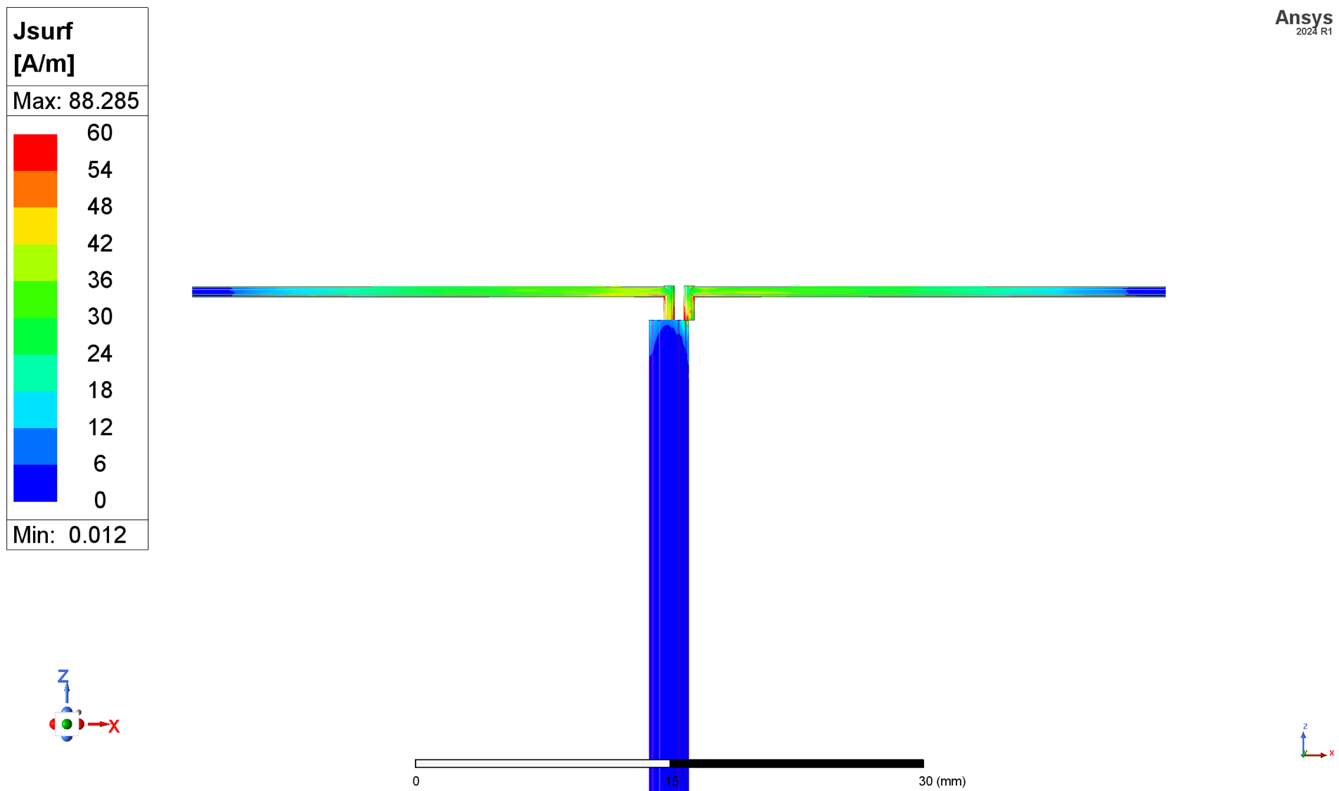

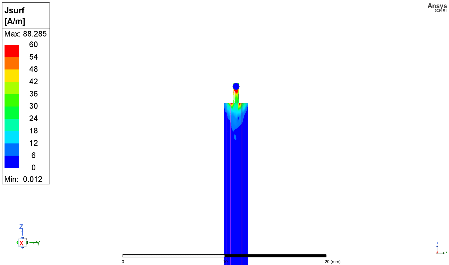
From the front view, you can see that the current nodes are at the ends of the elements and is highest at the feed, as one would expect for a 1/2 wavelength dipole. Also evident is current flow on the coax feed line of the non-balun dipole, as expected. An antenna’s radiation pattern is determined by the spatial distribution, magnitude, and phase of the currents flowing on the antenna structure. There are three main regions extending out from the antenna radiative elements:
1. Reactive Near-Field Region
- Definition: This is the region closest to the antenna where the reactive (non-radiative) fields dominate. These fields store energy but do not contribute to radiation.
- Distance: Extends approximately
, where:
- R: Distance from the antenna.
- D: Maximum dimension of the antenna.
- λ: Wavelength of the operating frequency.
- Characteristics:
- Electric and magnetic fields are not in phase and vary rapidly with distance.
- Energy oscillates back and forth between the antenna and the surrounding space rather than radiating away.
- Significance: Important for understanding antenna impedance and coupling with nearby objects.
2. Radiative Near-Field Region (Fresnel Region)
- Definition: This region is farther from the antenna than the reactive near-field, where radiative fields start to dominate, but the field pattern is not fully formed.
- Distance: Extends from the edge of the reactive near-field to approximately
.
- Characteristics:
- The field strength and phase vary significantly with distance and direction.
- The radiation pattern is complex and not yet fully developed.
- Significance: Used in applications like focusing antennas, phased arrays, or near-field measurements.
3. Far-Field Region (Fraunhofer Region)
- Definition: This is the region farthest from the antenna, where the radiation pattern is fully formed, and the electromagnetic fields behave as plane waves.
- Distance: Starts at approximately
.
- Characteristics:
- Electric and magnetic fields are orthogonal to each other and to the direction of propagation.
- The angular distribution of power is stable and does not change with distance.
- Field strength decreases proportionally to
.
- Significance: Most antenna radiation patterns and gain measurements are taken in this region.
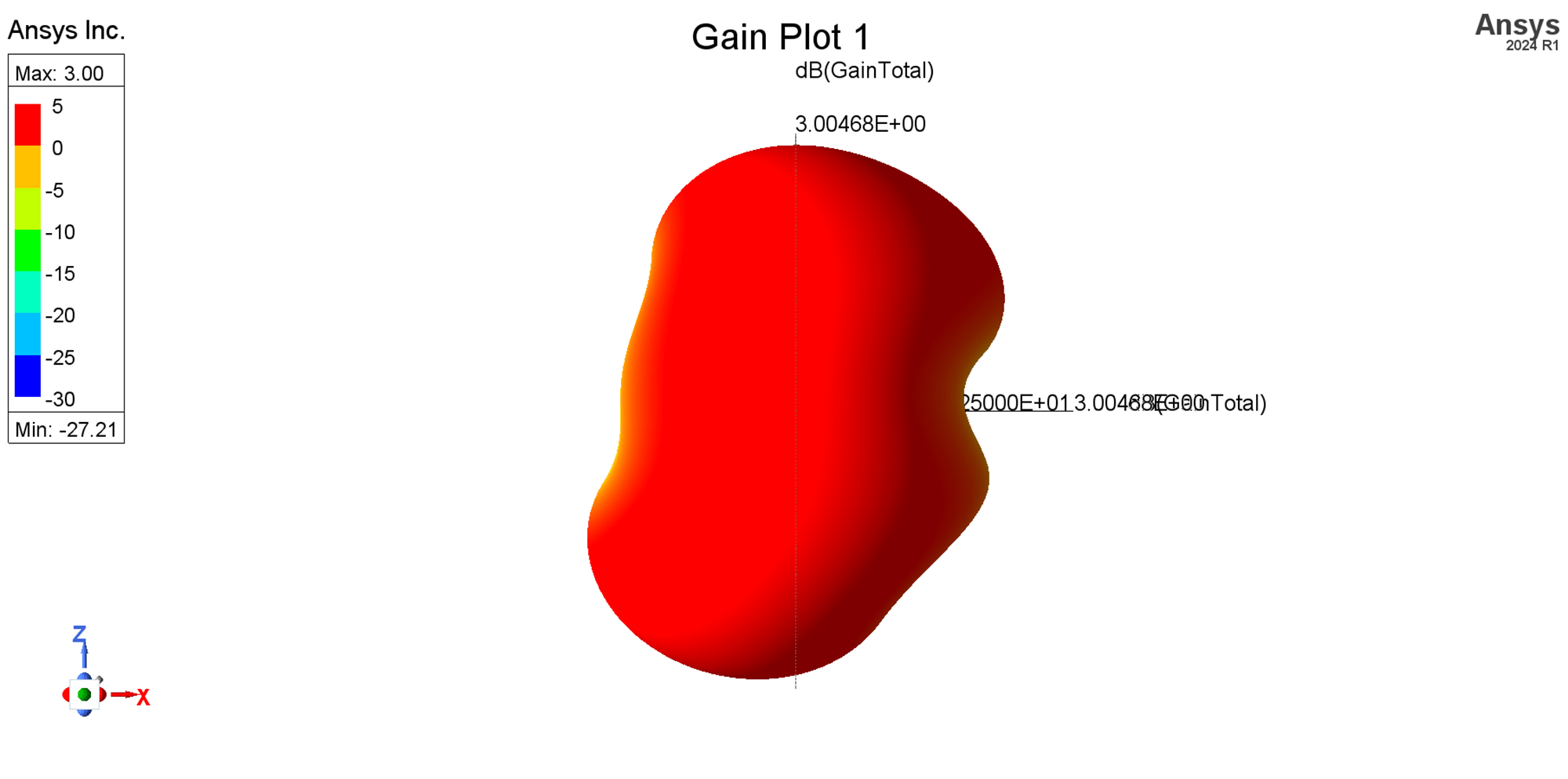
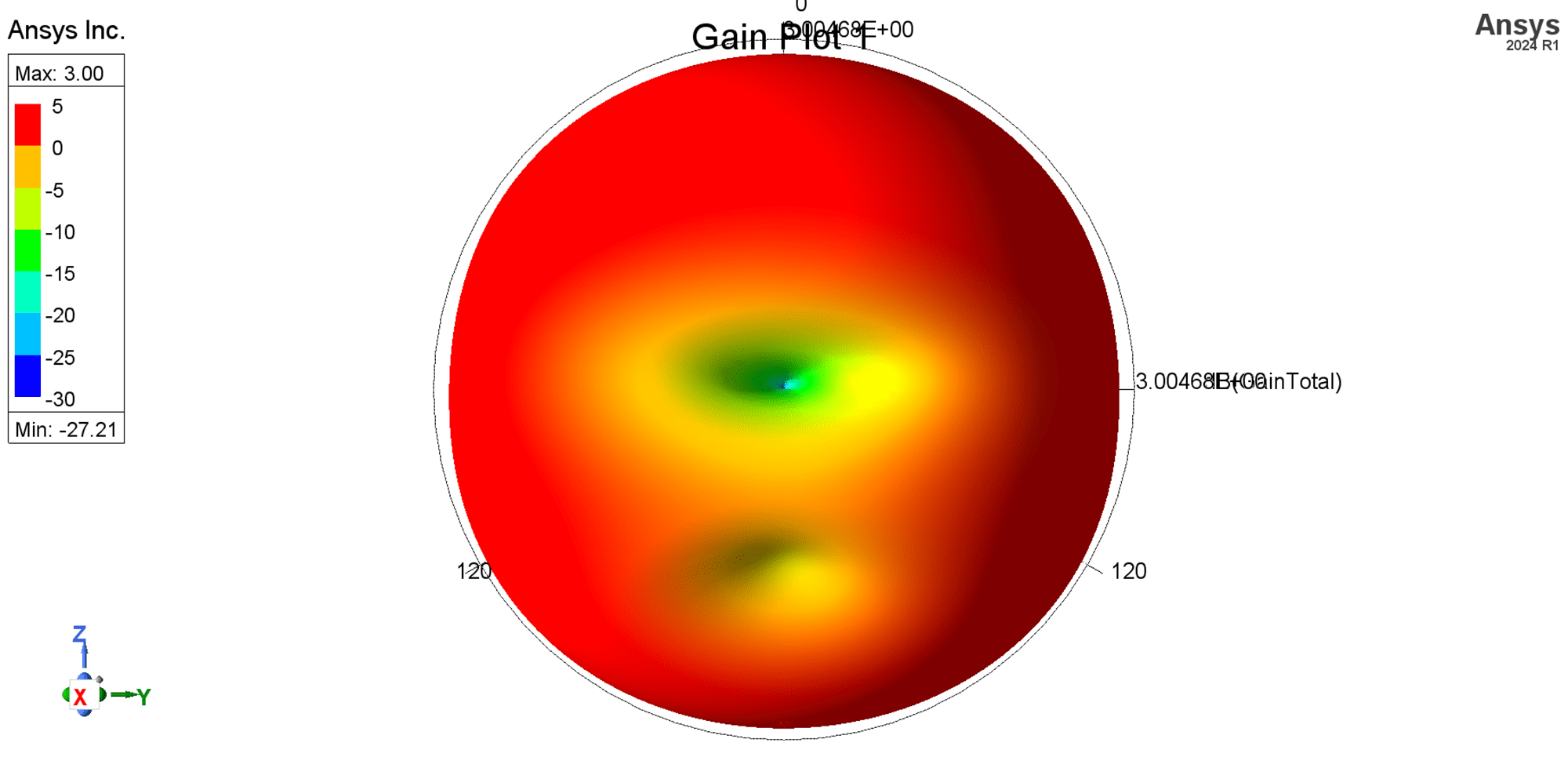
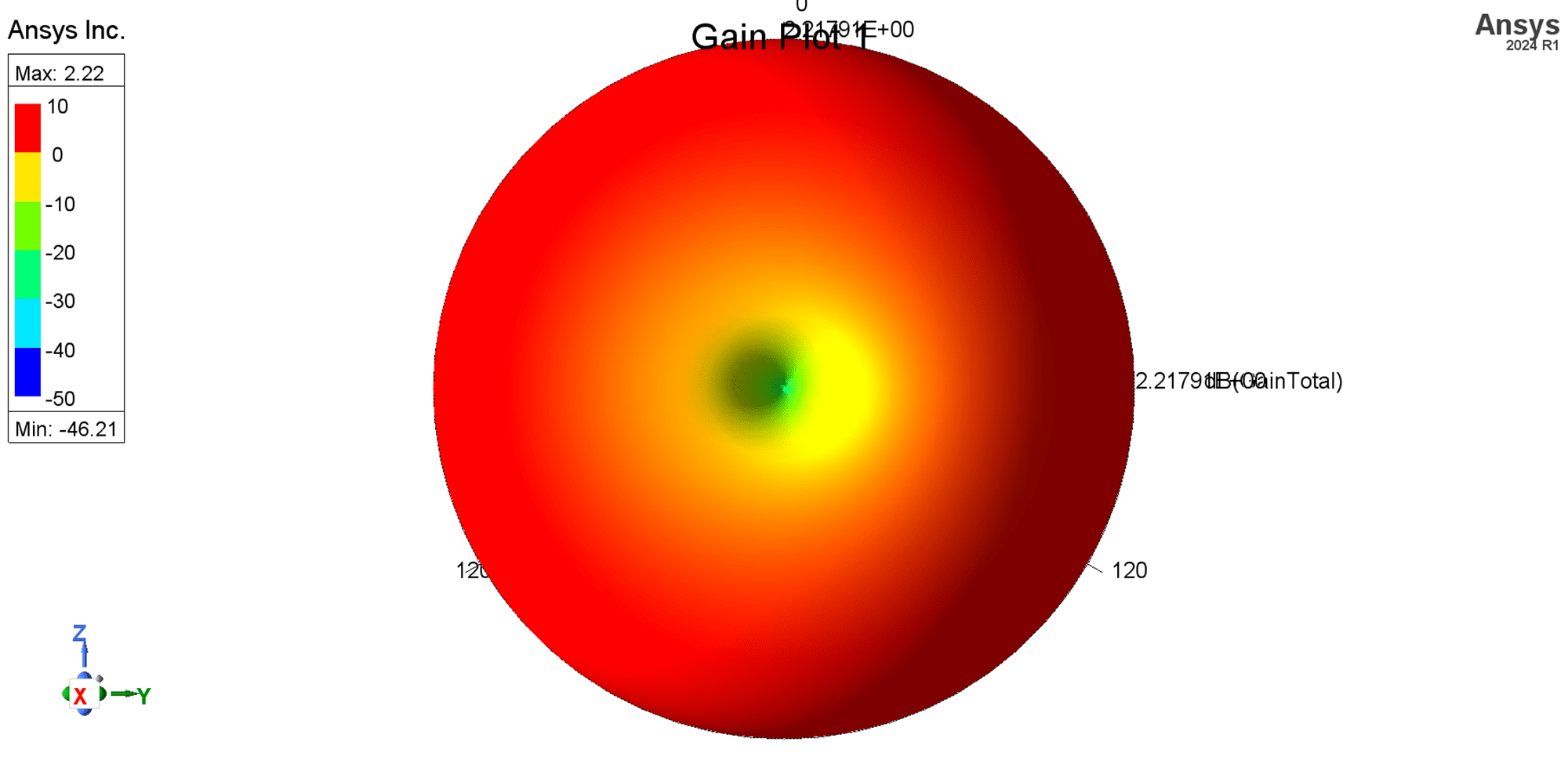
If we visualize the far-field region of the antennas with and without the choke balun, you can clearly see the effects of the uneven current distribution on the radiation pattern. The balun forces the current to be confined to the radiative dipole elements, resulting in a classic 1/2 wave dipole pattern, while the antenna without the balun has a distorted pattern.

Worth noting is that this is a dipole in free space with no ground plane. If we were to add a ground plane at distances greater than 
In conclusion, using a choke balun of the appropriate design and size can significantly improve the performance of antennas fed by coaxial cable by suppressing common-mode currents and preserving the intended radiation pattern. For a half-wave dipole (approximately 73 ohms) fed by a 50-ohm coaxial cable, a 1:1.5 balun is ideal to achieve proper impedance matching and improve VSWR. While toroidal transformers are not practical at microwave frequencies, alternative methods such as air-core choke baluns or PCB-based baluns with controlled impedance components can provide excellent performance. For microwave applications, PCB microstripline antennas with integrated baluns are highly efficient and well-suited for modern designs.