A few years ago, I acquired a box of Vaisala RS80-15G radiosondes from eBay. A radiosonde is typically attached to a helium or hydrogen balloon and released into the atmosphere. As it ascends, it measures atmospheric pressure, temperature, and humidity and transmits that data back to a ground receiving station. These observations are foundational for weather forecasting.
In the Vaisala RS80-15G, processing is intentionally split such that the radiosonde performs only minimal onboard functions—sampling meteorological sensors, tracking GPS L1 C/A signals to extract limited position or Doppler observables, time-tagging the measurements, and transmitting a low-rate telemetry stream—while all computationally intensive tasks are deferred to the ground system. The ground station demodulates and decodes the data, derives winds by differentiating the GPS observables over time and removing the known ascent rate, and applies filtering, quality control, and physical consistency checks to generate the final vertical wind profile. This architecture reflects a design philosophy optimized for low power, short mission duration, and high reliability in extreme environments, in contrast to modern radiosondes (e.g., Vaisala RS41), which perform full multi-constellation GNSS position-velocity-time solutions and some validation onboard, reducing reliance on ground-based processing while enabling higher accuracy and robustness.
While the DSP techniques are interesting, the helical GPS antenna was of particular interest to me.


The antenna appears to be a quadrifilar helix antenna (QHA) which is a compact antenna consisting of four helical conductors arranged symmetrically around a central axis and driven with specific phase relationships to produce right-hand circular polarization (RHCP). For GPS applications, this geometry naturally matches the polarization of GPS satellite signals and produces a broad, hemispherical radiation pattern with good gain at low elevation angles, where satellites are often hardest to receive. As a result, QHAs offer stable reception regardless of antenna orientation, reduced sensitivity to multipath and polarization mismatch, and reliable performance on small, moving platforms such as radiosondes, where maintaining a fixed antenna orientation is impractical.
To isolate the antenna for measurements, I cut the circuit board off at the antenna feed, attached an SMA connector and connected it to my Signal Hound Scalar Network Analyzer to measure S11.

Notice the first resonance at 1640 MHz is considerably higher than the 1575.42 MHz L1 C/A frequency (-64.58 MHz), which would normally be a problem. The measured return loss of the antenna at the L1 frequency appears poor when evaluated as a standalone 50-Ω device, which is probably a consequence of system-level design choices rather than a defective radiator. I suspect the antenna is tightly integrated with the radiosonde enclosure, internal PCB ground, battery pack, and what appears (from the circuit photo) to be an embedded low-noise amplifier (LNA). It therefore may not be intended to present a well-matched 50-Ω impedance when removed from its operational environment. The effective electrical length, resonance, and impedance are strongly influenced by the surrounding structure and by common-mode currents on the feed, which can significantly distort bench measurements. Moreover, because GPS is a receive-only, noise-limited system, antenna matching is frequently optimized for polarization purity, sky coverage, and minimum system noise figure rather than for deep return-loss nulls at the L1 center frequency. As a result, this antenna might be exhibiting unimpressive S-parameter performance for the L1 frequency in isolation while still delivering adequate signal-to-noise ratio and reliable satellite tracking in flight.
I decided to create a model of the antenna it in the Ansys HFSS software, keeping the dimensions and electrical connections as close as possible to the original. I used a digital caliper to measure the board and elements.
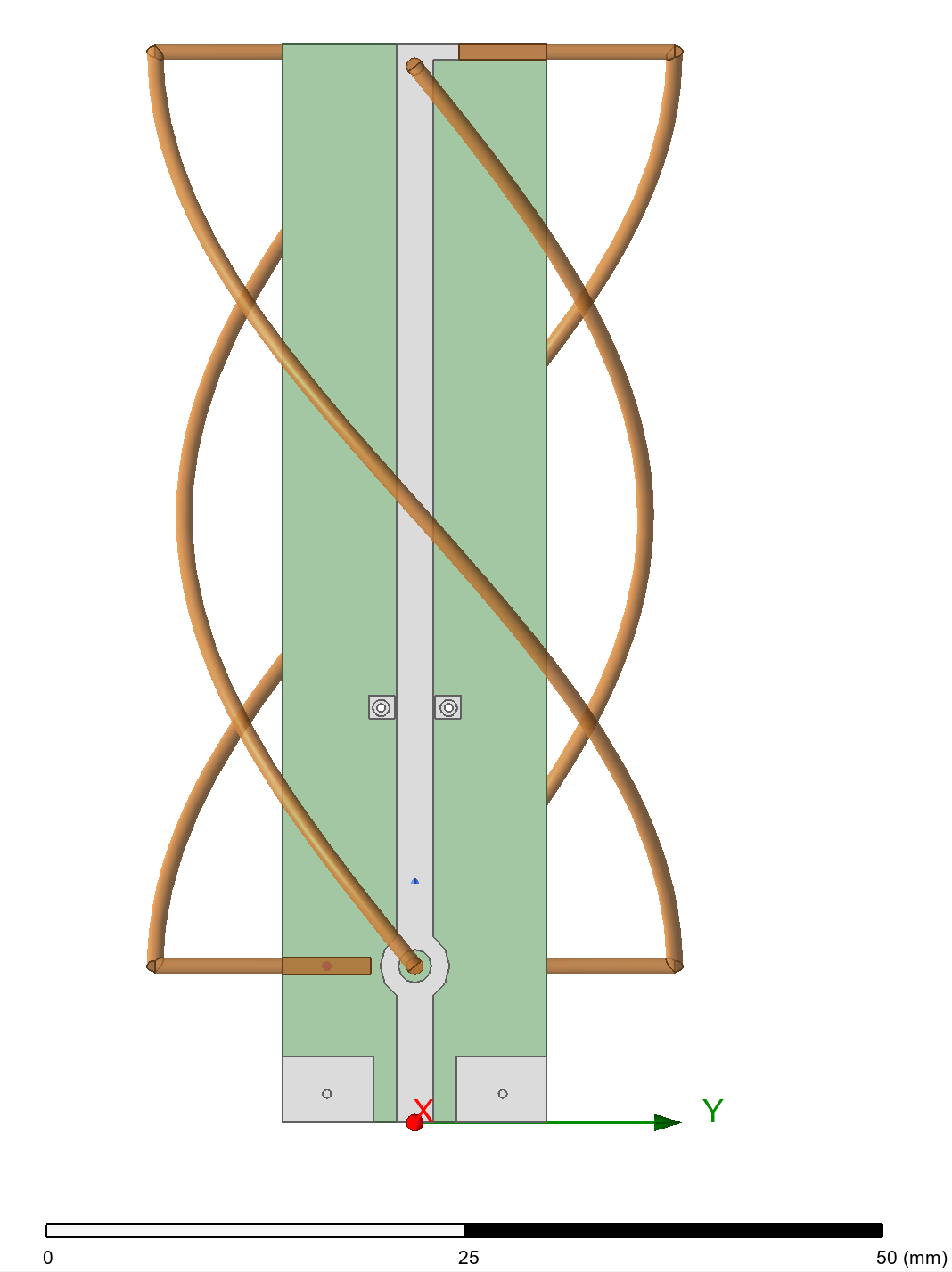

Of course, there are plenty of unknowns, including the dielectric constant of the PCB, materials used, etc. I chose to assume a 50 ohm microstrip construction and similarly characteristic feed impedance. I opted for a terminal network solution in HFSS. Below are the results of the simulation.


Analysis
The simulation results in HFSS provide a compelling look into the Quadrifilar Helix Antenna’s (QHA) specialized performance characteristics. While the physical measurements initially showed a small resonance offset for the L1 band, the modeled radiation patterns confirm the design’s inherent strengths: a remarkably broad, hemispherical beamwidth and excellent RHCP polarization purity. The 3D gain plots illustrate how the QHA maintains consistent coverage across the sky, effectively mitigating the signal fading that would plague a standard dipole on a tumbling radiosonde. Furthermore, the high ratio of Right-Hand Circular Polarization (RHCP) to Left-Hand Circular Polarization (LHCP) confirms that the geometry is finely tuned for the GPS satellites RHCP polarization, ensuring that the receiver locks onto direct line-of-sight satellite signals even in challenging atmospheric conditions.
Final Thoughts
Beyond its original role in the radiosonde, this QHA architecture serves as an excellent blueprint for custom RF applications. The beauty of the quadrifilar design lies in its geometric scalability; by proportionally adjusting the helical winding lengths and the diameter of the supporting structure, this model can be easily retuned for other critical bands. Specifically, scaling this design for ADS-B at 1090 MHz would yield a high-performance, compact antenna perfect for ground station receivers or UAV-based transponders. Whether it is for GNSS, satellite communications, or aircraft tracking, the foundational work of modeling this salvaged component opens the door to a wide array of high-reliability, circularly polarized antenna designs.